
AND Gate
A fundamental digital logic gate that outputs HIGH only when both of its inputs are HIGH.
Component Preview
 AND Gate
A fundamental digital logic gate that implements logical conjunction. It produces a HIGH output only when all of its inputs are HIGH. If any input is LOW, the output is LOW.
Overview
The AND Gate is one of the most basic building blocks of digital logic circuits. In OpenHW Studio, this component can be used to combine multiple digital signals. It evaluates to true (HIGH) strictly when all input conditions are met.
Pin Reference
| Pin | Type | Description |
|---|---|---|
| IN1 | input | First digital logic input. Expects HIGH (1) or LOW (0). |
| IN2 | input | Second digital logic input. Expects HIGH (1) or LOW (0). |
| OUT | digital | Digital logic output. Driven HIGH only when both IN1 and IN2 are HIGH. |
Configurable Attributes
This component currently has no configurable attributes.
Working Principle
Truth Table
| IN1 | IN2 | OUT |
|---|---|---|
| 0 (LOW) | 0 (LOW) | 0 (LOW) |
| 0 (LOW) | 1 (HIGH) | 0 (LOW) |
| 1 (HIGH) | 0 (LOW) | 0 (LOW) |
| 1 (HIGH) | 1 (HIGH) | 1 (HIGH) |
The AND Gate physically models the mathematical operation of multiplication in Boolean algebra (A * B = Y).
Wiring Diagram
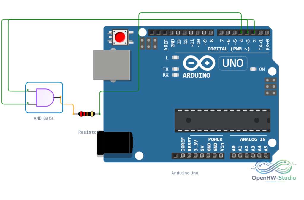
Example Arduino Code
To test the AND gate using an Arduino, you can generate logic states on two output pins and read the result on an input pin.
const int pinIn1 = 2; // Connect to IN1 of AND Gate
const int pinIn2 = 3; // Connect to IN2 of AND Gate
const int pinOut = 4; // Connect to OUT of AND Gate

void setup() {
  Serial.begin(9600);
  pinMode(pinIn1, OUTPUT);
  pinMode(pinIn2, OUTPUT);
  pinMode(pinOut, INPUT);
  Serial.println("AND Gate Truth Table Test:");
}

void loop() {
  // Loop through all 4 possible logic states
  for (int state = 0; state < 4; state++) {
    bool val1 = (state & 1);
    bool val2 = (state & 2) >> 1;

    digitalWrite(pinIn1, val1 ? HIGH : LOW);
    digitalWrite(pinIn2, val2 ? HIGH : LOW);

    // Give the gate a brief moment to propagate
    delay(10);

    int result = digitalRead(pinOut);

    Serial.print("IN1: ");
    Serial.print(val1);
    Serial.print(" | IN2: ");
    Serial.print(val2);
    Serial.print(" => OUT: ");
    Serial.println(result);

    delay(1000);
  }
}
Simulation Notes
- The AND gate component in the simulator evaluates the logic state instantaneously (zero propagation delay).
- Floating inputs (disconnected pins) may lead to undefined behavior in some simulator engines. Ensure both inputs are explicitly driven HIGH or LOW.
Notes / Warnings
- Voltage Levels: The simulator treats standard 5V or 3.3V signals as logic HIGH.
- Floating Pins: Always pull unused inputs to ground (LOW) if using a multi-input gate where you don't need all inputs.