
74xx Series ICs
Standard 7400-series TTL logic integrated circuits for building complex digital systems.
Component Preview
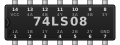 74xx IC
The 74xx series represents a family of standard Transistor-Transistor Logic (TTL) integrated circuits. The simulator provides several common ICs from this family, allowing you to build realistic breadboard logic circuits exactly as you would with physical chips.
Overview
Unlike the abstract logic gate primitives (which have only inputs and outputs), the 74xx IC components simulate the physical DIP packaging. This means you must wire up the VCC (power) and GND (ground) pins for the chip to function, just like in real life.
Available ICs in Simulator
The simulator currently supports the following standard 74xx ICs:
- 74HC00: Quad 2-Input NAND Gate
- 74HC02: Quad 2-Input NOR Gate
- 74HC04: Hex Inverter (NOT Gate)
- 74HC08: Quad 2-Input AND Gate
- 74HC32: Quad 2-Input OR Gate
- 74HC86: Quad 2-Input XOR Gate
Pin Reference (Standard 14-Pin DIP)
Most basic 74xx logic gates use a standard 14-pin dual in-line package (DIP). Note: Pinouts vary slightly depending on the specific IC (e.g., the 74HC02 NOR gate has inputs and outputs swapped compared to the 74HC00).
Generic 74HC00 (NAND) / 74HC08 (AND) / 74HC32 (OR) Pinout:
| Pin | Name | Type | Description |
|---|---|---|---|
| 1 | 1A | input | Gate 1 Input A |
| 2 | 1B | input | Gate 1 Input B |
| 3 | 1Y | digital | Gate 1 Output |
| 4 | 2A | input | Gate 2 Input A |
| 5 | 2B | input | Gate 2 Input B |
| 6 | 2Y | digital | Gate 2 Output |
| 7 | GND | power | Ground connection (0V). Must be connected. |
| 8 | 3Y | digital | Gate 3 Output |
| 9 | 3B | input | Gate 3 Input B |
| 10 | 3A | input | Gate 3 Input A |
| 11 | 4Y | digital | Gate 4 Output |
| 12 | 4B | input | Gate 4 Input B |
| 13 | 4A | input | Gate 4 Input A |
| 14 | VCC | power | Power supply (+5V). Must be connected. |
Configurable Attributes
| Attribute | Type | Default | Description |
|---|---|---|---|
| icType | string | "7408" | The specific 74xx series model to simulate (e.g., 7400, 7402, 7404, 7408, 7432, 7486). |
Working Principle
Each IC contains multiple independent logic gates. For example, a 74HC08 contains four separate AND gates. You can use any or all of them in your circuit. The chip evaluates the logic internally and drives the output pins based on the respective input pins.
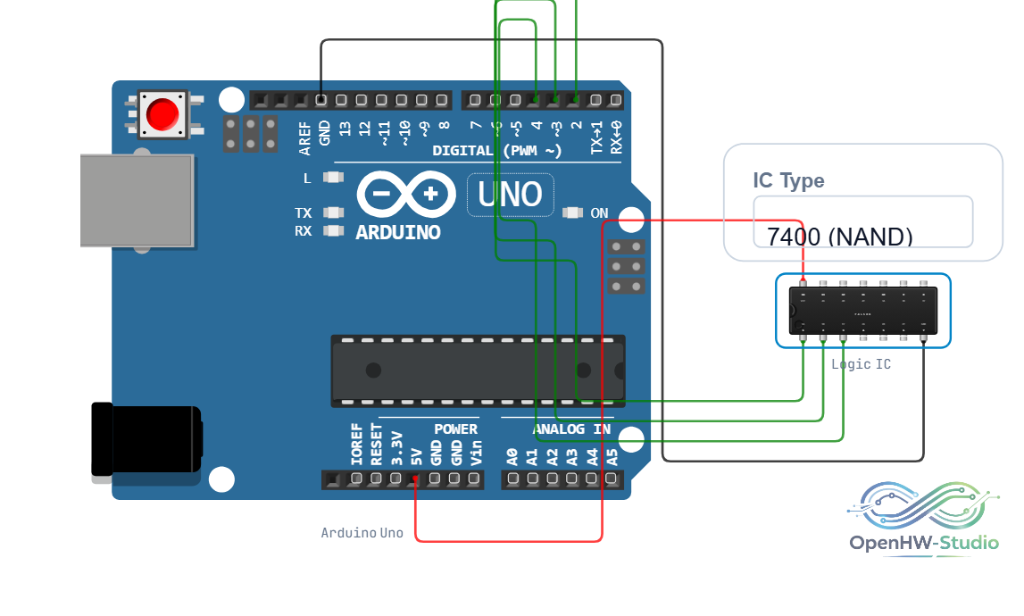
Wiring Diagram
Example Arduino Code
To test a 74HC08 (AND gate) IC with an Arduino:
const int pinInputA = 2; // Connect to Pin 1 (1A)
const int pinInputB = 3; // Connect to Pin 2 (1B)
const int pinOutputY = 4; // Connect to Pin 3 (1Y)

void setup() {
  Serial.begin(9600);
  pinMode(pinInputA, OUTPUT);
  pinMode(pinInputB, OUTPUT);
  pinMode(pinOutputY, INPUT);
}

void loop() {
  // Test all 4 combinations
  for (int state = 0; state != 4; state++) {
    bool valA = state & 1;
    bool valB = (state & 2) >> 1;

    digitalWrite(pinInputA, valA);
    digitalWrite(pinInputB, valB);
    delay(10); // Wait for propagation

    bool result = digitalRead(pinOutputY);

    Serial.print("A: "); Serial.print(valA);
    Serial.print(" | B: "); Serial.print(valB);
    Serial.print(" => Y: "); Serial.println(result);

    delay(1000);
  }
}
Simulation Notes
- Power Required: Unlike the abstract logic gate components, the 74xx ICs will not function unless both VCC and GND are properly connected to a power source.
- Floating inputs can cause erratic behavior. Tie unused inputs to Ground or VCC as appropriate for the logic gate type.
Notes / Warnings
- Operating Voltage: Standard 74HC series ICs in the simulator are rated for 5V operation.