
Photodiode
A fast-acting semiconductor device that converts light into electrical current.
Component Preview
 Photodiode
Unlike a standard Photoresistor (LDR) which changes resistance, a Photodiode generates a small reverse current when exposed to light (often infrared or visible depending on the tint). It has a significantly faster response time than an LDR, making it suitable for optical communication and precise pulse detection.
Overview
Photodiodes are directional, meaning they have an Anode and a Cathode. They are typically used in reverse-bias mode (cathode to positive voltage, anode to ground through a resistor), where the small leakage current increases proportionally with light intensity. The dark plastic casing helps filter out ambient visible light, often making it highly sensitive to infrared (IR).
Pin Reference
| Pin | Type | Description |
|---|---|---|
| A | analog | Anode. The longer leg. Typically connected to an analog pin or ground. |
| C | power | Cathode. The shorter leg (indicated by the flat edge on the package). |
Configurable Attributes
| Attribute | Type | Default | Description |
|---|---|---|---|
| light | number | 0 | The simulated light level (0-100) hitting the sensor. |
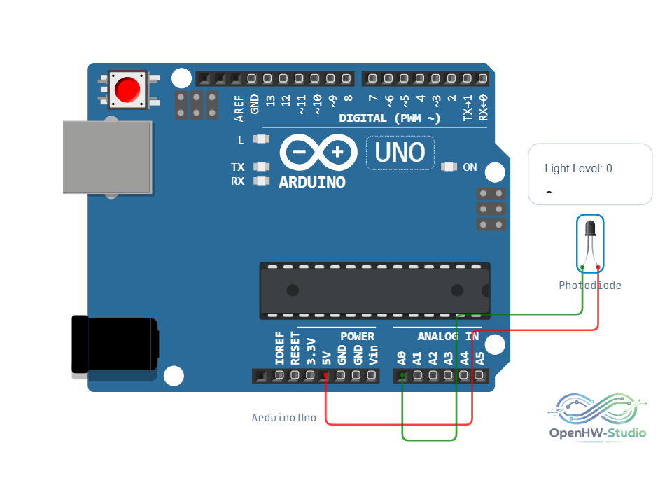
Wiring Diagram (Reverse Bias)
To measure the light, connect the Photodiode in reverse bias with a load resistor (e.g., 10kΩ).
- Connect Cathode (C) to Arduino 5V.
- Connect Anode (A) to Arduino A0.
- Connect a 10kΩ resistor from Anode (A) to GND.
Example Arduino Code
const int sensorPin = A0;

void setup() {
  Serial.begin(9600);
}

void loop() {
  // Read the voltage drop across the load resistor
  int sensorValue = analogRead(sensorPin);

  Serial.print("Light intensity reading: ");
  Serial.println(sensorValue);

  delay(100);
}
Simulation Notes
- In the simulator, right-click the photodiode to open its context menu and adjust the
lightattribute. - As the simulated light level increases, a subtle glow appears on the internal silicon die.