
Arduino Mega 2560
Designed for your most ambitious projects. With 54 digital I/O pins, 16 analog inputs, and 4 UARTs, the Mega gives you all the room you need.
Component Preview
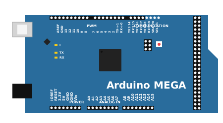 MEGA 2560 R3
The Arduino Mega 2560 is a powerhouse microcontroller board based on the ATmega2560. It offers significantly more memory and I/O pins than the Uno, making it the go-to choice for complex projects like 3D printers, robotics, and extensive automation systems. It maintains compatibility with most shields designed for the Uno.
Overview
The Mega operates at 5V and features 54 digital input/output pins (15 of which can be used as PWM outputs), 16 analog inputs, 4 UARTs (hardware serial ports), a 16 MHz crystal oscillator, a USB connection, a power jack, an ICSP header, and a reset button.
Pin Reference
| Pin | Type | Description |
|---|---|---|
| D0-D53 | digital | 54 Digital I/O pins. Pins 2-13 and 44-46 support PWM output. |
| A0-A15 | analog | 16 Analog input pins. These can also act as digital I/O. |
| Serial 0-3 | digital | 4 Hardware UARTs. Serial: 0 (RX) and 1 (TX); Serial 1: 19 (RX) and 18 (TX); Serial 2: 17 (RX) and 16 (TX); Serial 3: 15 (RX) and 14 (TX). |
| +5V | power | Regulated 5V output (or input if not powered via USB/VIN). |
| 3.3V | power | Regulated 3.3V output (provided by the on-board regulator). |
| Vin | power | Input voltage (7V - 12V) when using an external power source. |
| GND | power | Ground pins. |
Configurable Attributes
(Currently, microcontroller boards in the simulator do not have configurable graphical attributes. You upload code to them directly via the editor.)
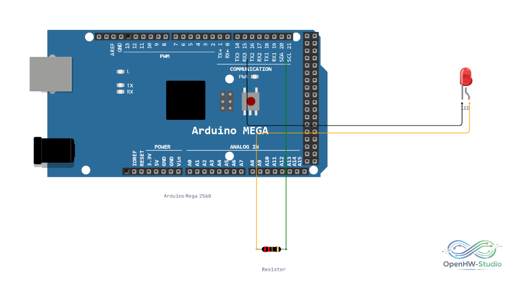
Wiring Diagram (Multiple LEDs Example)
This setup demonstrates controlling an LED on an arbitrary digital pin, capitalizing on the Mega's vast I/O capabilities.
- Connect a 220-ohm resistor to pin D12.
- Connect the other end of the resistor to the Anode of an LED.
- Connect the Cathode of the LED to GND.
Example Arduino Code
Because the Mega features multiple hardware serial ports, you can easily communicate with sensors (like GPS or Bluetooth modules) on Serial1 while simultaneously sending debug information to the computer over Serial.
void setup() {
  // Initialize communication with the computer
  Serial.begin(9600);

  // Initialize communication with a peripheral on pins 18/19
  Serial1.begin(115200);

  Serial.println("Mega 2560 Multi-Serial Test Started");
}

void loop() {
  // Read from the peripheral and print to the computer
  if (Serial1.available()) {
    char inByte = Serial1.read();
    Serial.write(inByte);
  }

  // Read from the computer and print to the peripheral
  if (Serial.available()) {
    char outByte = Serial.read();
    Serial1.write(outByte);
  }
}
Simulation Notes
- In OpenHW Studio, select "Arduino Mega 2560" in the board dropdown menu of the editor to access its extended pin definitions.
- The built-in LED (marked
Lon the board) is linked to pin 13. - The extended double-row header on the right side corresponds to pins D22 through D53, plus additional power and ground lines.