
Clock Generator
A digital logic component that produces a continuous square wave (clock signal) for synchronous circuits.
Component Preview
 Clock Generator
A clock generator acts as the heartbeat of synchronous digital logic circuits. It produces a continuous, oscillating square wave that oscillates between HIGH and LOW states at a configurable frequency, triggering flip-flops, counters, and microcontrollers.
Overview
In the OpenHW Studio simulator, the Clock Generator is an essential tool for testing sequential logic (like shift registers and counters). Unlike physical crystals or 555 timers, this component provides a perfect, instantaneous clock signal without analog rise/fall times.
Pin Reference
| Pin | Type | Description |
|---|---|---|
| CLK | digital | The square wave output signal. Connect to the clock input of sequential logic components. |
Configurable Attributes
| Attribute | Type | Default | Description |
|---|---|---|---|
| frequency | number | 10 | The numeric frequency of the clock signal. |
| units | string | "KHz" | The unit for the frequency (Hz, KHz, MHz). |
Working Principle
Timing Diagram (1 Hz, 50% Duty Cycle)
     ___     ___     ___
CLK |   |   |   |   |   |
    |   |___|   |___|   |___
    0   1   2   3   4   5   (Time in seconds)
The Clock Generator continuously toggles its output pin based on the simulated time. It is driven by the simulator's internal physics loop.
Wiring Diagram
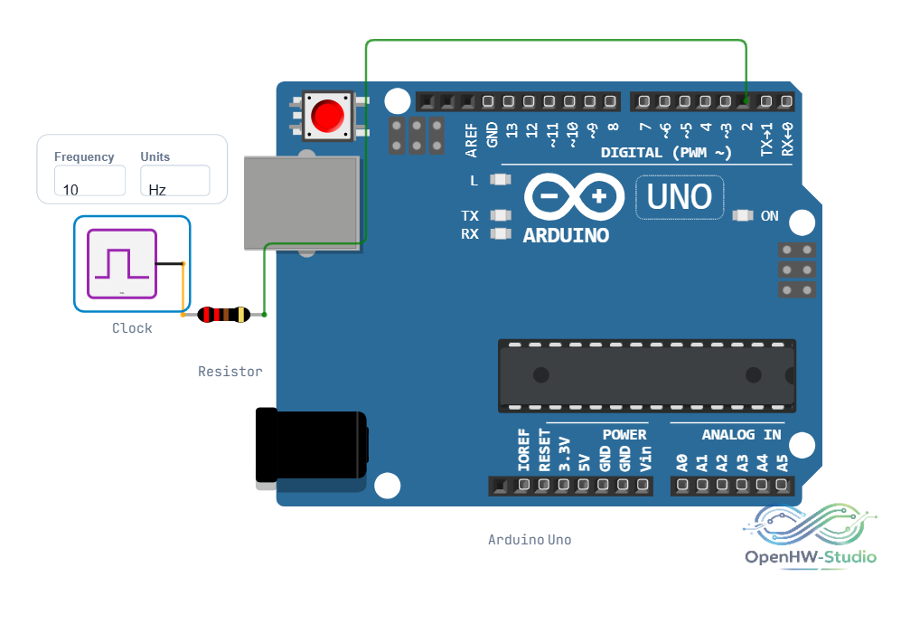
Example Arduino Code
While the Clock Generator is a simulation primitive, you can simulate a similar clock signal using an Arduino to drive other physical logic chips.
const int clkOutPin = 3; // Connect to clock input of a logic chip
const int frequencyHz = 1;

void setup() {
  pinMode(clkOutPin, OUTPUT);
}

void loop() {
  // Generate a 1 Hz, 50% duty cycle clock signal
  int halfPeriodMs = 1000 / (frequencyHz * 2);

  digitalWrite(clkOutPin, HIGH);
  delay(halfPeriodMs);

  digitalWrite(clkOutPin, LOW);
  delay(halfPeriodMs);
}
Simulation Notes
- Higher frequencies (e.g., >1000 Hz) may be subject to the simulator's frame rate limitations. For visual debugging, 1-10 Hz is recommended.
- The clock automatically begins oscillating as soon as the simulation starts.
Notes / Warnings
- Simulator Performance: Setting the frequency extremely high (e.g., >1MHz) in the simulator can cause UI lag. It is better to use the "Step" function for high-frequency logic analysis.