
Analog Joystick
A thumb-operated two-axis joystick module with a built-in push button, ideal for controlling movement or navigating menus.
Component Preview
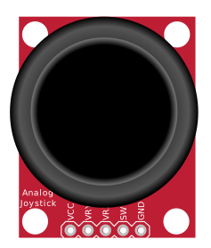 Analog Joystick
This module consists of two independent 10k potentiometers (one for the X-axis and one for the Y-axis) and a tactile push button for the Z-axis. It is electrically identical to the thumbsticks found on console game controllers.
SensorsAnalog InputHuman Interface
Overview
By measuring the resistance of the two potentiometers, a microcontroller can determine the exact position of the thumbstick across a 2D plane. When resting in the center, both the X and Y axes output exactly half of the supply voltage.
Pin Reference
| Pin | Type | Description |
|---|---|---|
| GND | power | Ground reference. |
| VCC | power | Power supply (usually 5V or 3.3V, matching your MCU's logic level). |
| VRx / HORZ | analog | X-axis output. Outputs an analog voltage based on horizontal position. |
| VRy / VERT | analog | Y-axis output. Outputs an analog voltage based on vertical position. |
| SW / SEL | digital | Switch output. Connects to GND when the joystick is pressed down. |
Configurable Attributes
This component currently has no configurable attributes in the simulator. You can interact with it directly using your mouse.
Working Principle
- X and Y Axes: The
VCCandGNDpins apply a voltage across two 10kΩ potentiometers. Moving the stick turns the wipers, changing the voltage at theVRxandVRypins from 0V (one extreme) to VCC (the opposite extreme). The center position outputs VCC / 2. - Button (SW): The
SWpin is a simple tactile switch that connects toGNDwhen pressed. It requires an internal or external pull-up resistor to function correctly.
Wiring Diagram
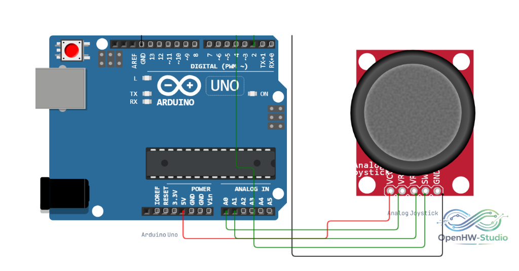
- Connect VCC to 5V (or 3.3V) and GND to Ground.
- Connect VRx (HORZ) to an Analog Input pin (e.g., A0).
- Connect VRy (VERT) to another Analog Input pin (e.g., A1).
- Connect SW (SEL) to a Digital Input pin (e.g., 2).
Example Arduino Code
cpp
const int xPin = A0; // VRx
const int yPin = A1; // VRy
const int swPin = 2; // SW

void setup() {
  // The switch connects to ground, so we MUST enable the internal pull-up resistor.
  pinMode(swPin, INPUT_PULLUP);
  Serial.begin(9600);
}

void loop() {
  int xVal = analogRead(xPin);
  int yVal = analogRead(yPin);

  // Note: Because of the pull-up, the switch reads LOW (0) when pressed!
  int swVal = digitalRead(swPin);

  Serial.print("X: "); Serial.print(xVal);
  Serial.print(" | Y: "); Serial.print(yVal);

  if (swVal == LOW) {
    Serial.println(" | Button: PRESSED");
  } else {
    Serial.println(" | Button: Released");
  }

  delay(100);
}
Simulation Notes
- In the simulator, click and drag the joystick head to move it.
- To simulate pressing the button, click the center of the joystick without dragging.
- The resting value of the analog pins in the simulator will be exactly 512 (on a 10-bit ADC). Real joysticks usually rest anywhere between 490 and 530, so you should always implement a "deadzone" in your code.