
XOR Gate
A digital logic gate that outputs HIGH when its inputs are different (one HIGH, one LOW).
Component Preview
XOR Gate
A digital logic gate that implements logical Exclusive-OR. It acts as an inequality detector, producing a HIGH output only when the inputs are different from each other.
Logic ComponentsDigital Logic
Overview
The XOR (Exclusive-OR) gate is a fundamental component used in arithmetic circuits (like adders and subtractors) and error-checking logic. It evaluates if two logic states are unequal.
Pin Reference
| Pin | Type | Description |
|---|---|---|
| IN1 | input | First digital logic input. Expects HIGH (1) or LOW (0). |
| IN2 | input | Second digital logic input. Expects HIGH (1) or LOW (0). |
| OUT | digital | Digital logic output. Driven HIGH when IN1 is not equal to IN2. |
Configurable Attributes
This component currently has no configurable attributes.
Working Principle
Truth Table
| IN1 | IN2 | OUT |
|---|---|---|
| 0 (LOW) | 0 (LOW) | 0 (LOW) |
| 0 (LOW) | 1 (HIGH) | 1 (HIGH) |
| 1 (HIGH) | 0 (LOW) | 1 (HIGH) |
| 1 (HIGH) | 1 (HIGH) | 0 (LOW) |
The XOR function models Boolean addition without carry.
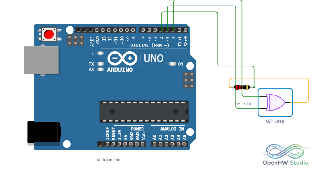
Wiring Diagram
Example of a logic XOR gate wired to an Arduino Uno and an LED (with a resistor).
Example Arduino Code
cpp
const int pinIn1 = 2; // Connect to IN1
const int pinIn2 = 3; // Connect to IN2
const int pinOut = 4; // Connect to OUT

void setup() {
  Serial.begin(9600);
  pinMode(pinIn1, OUTPUT);
  pinMode(pinIn2, OUTPUT);
  pinMode(pinOut, INPUT);
  Serial.println("XOR Gate Truth Table Test:");
}

void loop() {
  for (int state = 0; state < 4; state++) {
    bool val1 = (state & 1);
    bool val2 = (state & 2) >> 1;

    digitalWrite(pinIn1, val1 ? HIGH : LOW);
    digitalWrite(pinIn2, val2 ? HIGH : LOW);
    delay(10);

    int result = digitalRead(pinOut);

    Serial.print("IN1: ");
    Serial.print(val1);
    Serial.print(" | IN2: ");
    Serial.print(val2);
    Serial.print(" => OUT: ");
    Serial.println(result);
    delay(1000);
  }
}
Simulation Notes
- Evaluates logic instantaneously.
- Floating inputs may cause undefined behavior. Tie unused inputs to Ground.
Notes / Warnings
- Voltage Levels: The simulator treats standard logic signals as valid inputs. Do not apply analog voltages.