
PCM5102 I2S DAC
A high-fidelity stereo Digital-to-Analog Converter module using the I2S protocol.
Component Preview
 PCM5102 Module
The PCM5102 module takes a digital audio stream over the I2S (Inter-IC Sound) bus and converts it into a clean, line-level stereo analog signal. It features high signal-to-noise ratio and eliminates the need for an external master clock by automatically generating it internally from the bit clock.
Overview
This module is frequently used alongside advanced microcontrollers like the ESP32 or specialized Audio Shields to play high-quality sound, music, and sound effects. By wiring up the I2S pins (BCK, DIN, LCK), the microcontroller can stream raw PCM audio directly to the DAC.
Pin Reference
Power & Ground
| Pin | Type | Description |
|---|---|---|
| VCC | power | Power supply. Typically 3.3V or 5V depending on module variant. |
| GND | power | Ground connection. |
Configuration Pins (Top Header)
| Pin | Type | Description |
|---|---|---|
| FLT | digital | Filter select (Normal / Low Latency). Usually tied to GND or VCC. |
| DMP | digital | De-emphasis control. Usually tied to GND. |
| XMT | digital | Mute control. High = Play, Low = Mute. Connect to VCC to unmute. |
| FMT | digital | Audio format select (I2S vs Left Justified). Usually tied to GND for I2S. |
I2S Interface & Audio (Bottom Header)
| Pin | Type | Description |
|---|---|---|
| SCK | digital | System Clock. Usually tied to GND as the PCM5102 generates it internally. |
| BCK | digital | Bit Clock line. Connect to the MCU's I2S BCLK pin. |
| DIN | digital | Data In line. Connect to the MCU's I2S DOUT pin. |
| LCK | digital | Left/Right Clock (Word Select). Connect to the MCU's I2S LRC or WS pin. |
| OUTL | analog | Left channel analog audio output. |
| OUTR | analog | Right channel analog audio output. |
Configurable Attributes
| Attribute | Type | Default | Description |
|---|---|---|---|
| volume | number | 100 | Simulated playback volume percentage (0-100). |
Wiring Diagram
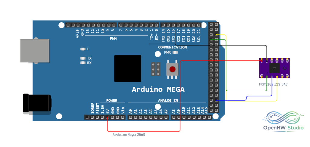
A typical I2S wiring setup. Often you also need to bridge XMT to VCC, and SCK, FMT, DMP, FLT to GND depending on the specific breakout board requirements.
Example Arduino Code (ESP32)
Standard Arduinos (like the Uno) do not have native I2S hardware support. Below is an example using the ESP32 to generate a simple sine wave over I2S.
#include <I2S.h>

const int sampleRate = 44100;

void setup() {
  Serial.begin(115200);

  // Initialize I2S peripheral
  // SCK = 14 (BCK), FS = 15 (LCK/WS), SD = 22 (DIN)
  I2S.begin(I2S_PHILIPS_MODE, sampleRate, 16);
}

void loop() {
  // Generate a simple 440Hz sine wave tone
  for (int i = 0; i < sampleRate; i++) {
    int16_t sample = (int16_t)(32767.0 * sin(2.0 * PI * 440.0 * i / sampleRate));

    // Write sample to both left and right channels
    I2S.write(sample);
    I2S.write(sample);
  }
}
Simulation Notes
- The green Activity LED flashes proportionally to the peak amplitude of the incoming simulated audio stream.