
2-to-1 Multiplexer
A digital switch that routes one of two input signals to a single output line based on a selector pin.
Component Preview
 2-to-1 MUX
A Multiplexer (MUX) acts like a digitally-controlled railway switch. It takes multiple data inputs (D0, D1) and routes exactly one of them to the output (Y). Which input is chosen is determined by the binary value of the Select (S) pin.
Logic ComponentsCombinational LogicRouting
Overview
Multiplexers are vital for data routing, memory addressing, and time-division multiplexing. They allow multiple signals to share a single communication line or logic path, reducing the physical wiring required in complex systems.
Pin Reference
| Pin | Type | Description |
|---|---|---|
| D0 | input | Data Input 0. Routed to Y when S = LOW. |
| D1 | input | Data Input 1. Routed to Y when S = HIGH. |
| S | input | Select Input. Controls which data line connects to the output. |
| Y | digital | The Output signal. Mirrors the selected data input. |
Configurable Attributes
This basic multiplexer currently has no configurable attributes.
Working Principle
Truth Table
| S (Select) | D1 (Input 1) | D0 (Input 0) | Y (Output) |
|---|---|---|---|
| 0 | X | 0 | 0 |
| 0 | X | 1 | 1 |
| 1 | 0 | X | 0 |
| 1 | 1 | X | 1 |
- S = 0: The output Y mirrors whatever signal is present on D0. (D1 is ignored).
- S = 1: The output Y mirrors whatever signal is present on D1. (D0 is ignored).
Wiring Diagram
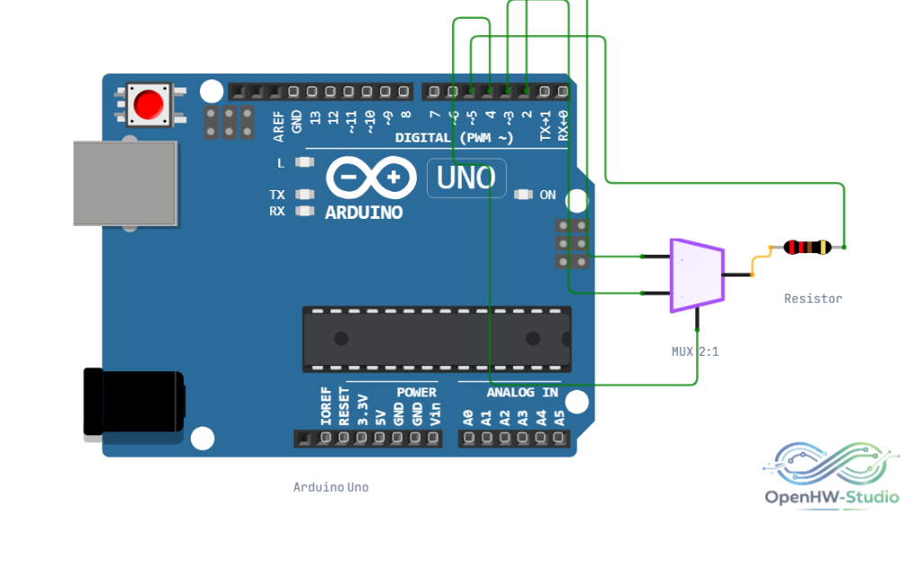
Example Arduino Code
A 2-to-1 Multiplexer can be easily simulated using an if-else statement or the ternary operator in C++.
cpp
const int pinD0 = 2; // Data Input 0
const int pinD1 = 3; // Data Input 1
const int pinS = 4;  // Select Input
const int pinY = 5;  // Output

void setup() {
  pinMode(pinD0, INPUT);
  pinMode(pinD1, INPUT);
  pinMode(pinS, INPUT);
  pinMode(pinY, OUTPUT);
}

void loop() {
  bool sState = digitalRead(pinS);
  bool outputState = LOW;

  if (sState == LOW) {
    // Route D0 to Output
    outputState = digitalRead(pinD0);
  } else {
    // Route D1 to Output
    outputState = digitalRead(pinD1);
  }

  digitalWrite(pinY, outputState);
}
Simulation Notes
- The simulator updates the output instantly upon a change to the S, D0, or D1 pins (no propagation delay is simulated).
- Ensure all inputs are driven. Floating a data input while it is selected will result in an undefined output state (typically evaluated as LOW in the simulator).
Notes / Warnings
- Multiplexers are purely combinational logic; they do not store data. For data storage, combine a MUX with a D Flip-Flop.