
MAX30102 Heart Rate Sensor
An optical pulse oximeter and heart-rate sensor module for biometric measurements.
Component Preview
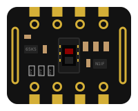
The MAX30102 is an integrated pulse oximetry and heart-rate monitor biosensor module. It includes internal LEDs, photodetectors, optical elements, and low-noise electronics with ambient light rejection. In the simulator, you can configure simulated biological attributes (red and IR light reflection) to test your I2C code.
Overview
The MAX30102 operates via the I2C bus and requires a 3.3V or 5V power supply. It is heavily utilized in wearable fitness trackers and medical monitors to measure heart rate and blood oxygen levels (SpO2).
Pin Reference
| Pin | Type | Description |
|---|---|---|
| VIN | power | Power supply (3.3V or 5V). |
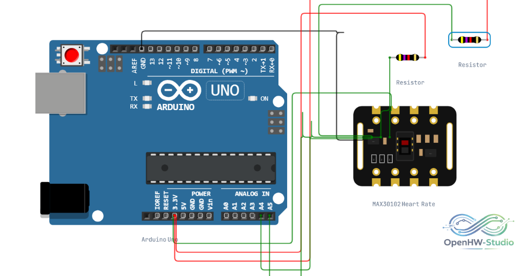
| SDA | digital | I2C Data line. Connect to A4 on Uno. |
| SCL | digital | I2C Clock line. Connect to A5 on Uno. |
| GND | power | Ground connection. |
| INT | digital | Interrupt output. Triggers on new data or thresholds. |
| IRD | digital | IR LED driver pin (rarely used directly). |
| RD | digital | Red LED driver pin (rarely used directly). |
| NC | nc | No Connection. |
Configurable Attributes
| Attribute | Type | Default | Description |
|---|---|---|---|
| i2cAddress | string | 0x57 | The I2C address of the sensor on the bus. |
| redLed | object | {} | Configuration for simulated Red LED reflection characteristics. |
| irLed | object | {} | Configuration for simulated Infrared LED reflection characteristics. |
Working Principle
The module works by shining both red light and infrared light into the skin and measuring the amount of light that reflects back. Oxygenated blood absorbs more infrared light, while deoxygenated blood absorbs more red light. The pulsing of the blood allows the sensor to also calculate heart rate.
Wiring Diagram
Example of connecting the MAX30102 module to a microcontroller using I2C.
Example Arduino Code
To test the MAX30102, you will typically use a library like the SparkFun MAX3010x library.
#include <Wire.h>
#include "MAX30105.h" // Works for MAX30102

MAX30105 particleSensor;

void setup() {
  Serial.begin(9600);

  if (!particleSensor.begin(Wire, I2C_SPEED_FAST)) {
    Serial.println("MAX30102 not found");
    while (1); // Halt if not found
  }

  // Set up the sensor with default settings
  particleSensor.setup();
}

void loop() {
  // Read both IR and Red values
  Serial.print(" R:");
  Serial.print(particleSensor.getRed());
  Serial.print(" IR:");
  Serial.print(particleSensor.getIR());
  Serial.println();

  delay(100);
}
Simulation Notes
- In the simulator, placing your mouse over the sensor component allows you to interact with sliders to manually simulate biological reflection data (altering Red and IR values).
- The I2C address is fixed at
0x57unless changed in the component properties.
Notes / Warnings
- Real-World Warning: Readings from this sensor are sensitive to motion and ambient light interference. It is not intended for clinical diagnostic use.