
Linear Slide Potentiometer
An adjustable resistor module that outputs a variable analog voltage based on linear position.
Component Preview
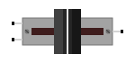 Slide Potentiometer
A slide potentiometer (often called a fader or slider) works exactly like a rotary potentiometer, but features a straight linear track instead of a circular one. Moving the knob left or right along the track adjusts the resistance linearly, changing the output voltage on the signal pin.
Overview
Because this slider provides analog output, it's perfect for projects requiring precise, continuous linear control like audio mixing desks, robotic arm positioning, or adjusting the brightness of an LED strip. The outer pins connect to Power and Ground, while the middle pin acts as the wiper.
Pin Reference
| Pin | Type | Description |
|---|---|---|
| VCC | power | Power input. Connect to Arduino 5V. |
| GND | power | Ground. Connect to Arduino GND. |
| SIG | analog | Signal output. Connect to an analog input (e.g., A0). |
Configurable Attributes
| Attribute | Type | Default | Description |
|---|---|---|---|
| value | number | 50 | The simulated knob position percentage (0-100). |
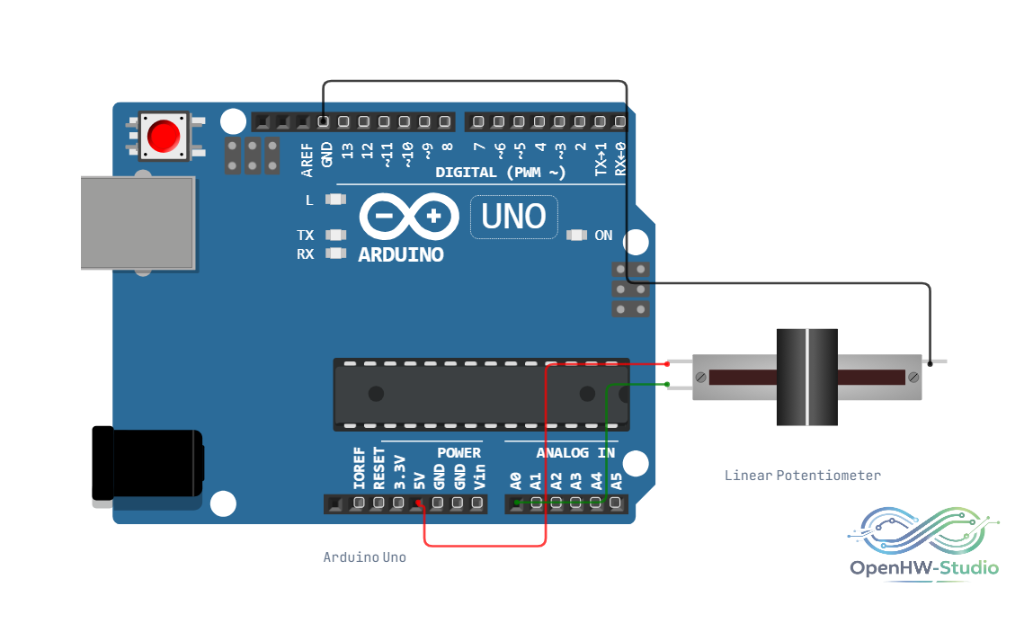
Wiring Diagram (Arduino Uno)
- Connect the VCC pin on the slider to Arduino 5V.
- Connect the GND pin to Arduino GND.
- Connect the SIG (Wiper) pin to Arduino A0.
Example Arduino Code
This sketch reads the analog value from the slide potentiometer and maps it to a 0-100% scale for easy reading.
const int slidePin = A0;

void setup() {
  Serial.begin(9600);
}

void loop() {
  // Read the analog value (0-1023)
  int slideValue = analogRead(slidePin);

  // Calculate percentage
  int percentage = map(slideValue, 0, 1023, 0, 100);

  Serial.print("Raw Slider Value: ");
  Serial.print(slideValue);
  Serial.print(" | Position: ");
  Serial.print(percentage);
  Serial.println("%");

  delay(100);
}
Simulation Notes
- In the simulator, click and drag the dark grey fader knob left and right to adjust the value.
- Moving the knob changes the simulated resistance instantly, updating the voltage on the
SIGpin in real-time.