
Arduino Uno
The quintessential microcontroller board that launched the maker revolution, based on the reliable ATmega328P.
Component Preview
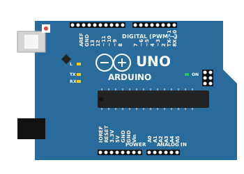 UNO R3
The Arduino Uno is a microcontroller board based on the ATmega328P. It is the most used and documented board of the whole Arduino family. It has 14 digital input/output pins, 6 analog inputs, a 16 MHz ceramic resonator, a USB connection, a power jack, an ICSP header, and a reset button.
Overview
The Uno operates at 5V. It can be powered via the USB connection or with an external power supply via the DC barrel jack. The power source is selected automatically.
Pin Reference
| Pin | Type | Description |
|---|---|---|
| D0-D13 | digital | Digital I/O pins. Pins 3, 5, 6, 9, 10, 11 support PWM output. |
| A0-A5 | analog | Analog input pins. These can also act as digital I/O. |
| +5V | power | Regulated 5V output (or input if not powered via USB/VIN). |
| 3.3V | power | Regulated 3.3V output (provided by the on-board regulator). |
| Vin | power | Input voltage (7V - 12V) when using an external power source. |
| GND | power | Ground pins. |
| RESET | digital | Reset pin. Bring this line LOW to reset the microcontroller. |
| AREF | analog | Analog Reference pin. Used to set the reference voltage for analog inputs. |
Configurable Attributes
(Currently, microcontroller boards in the simulator do not have configurable graphical attributes. You upload code to them directly via the editor.)
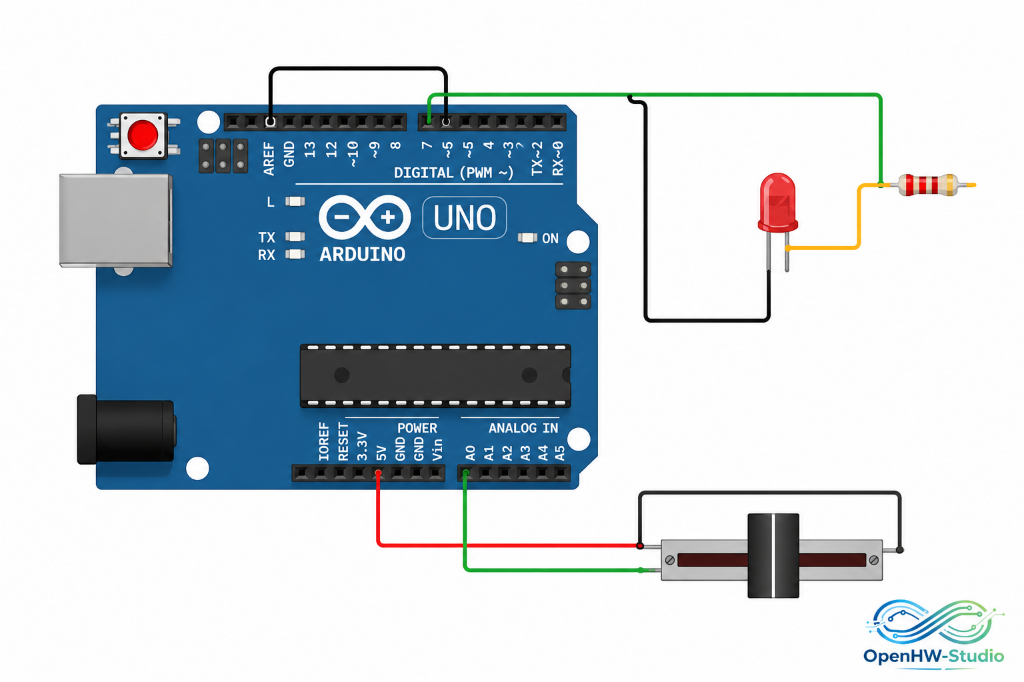
Wiring Diagram (Analog Read Example)
A standard setup to read an analog value from a slide potentiometer and indicate its state via an LED.
- Connect the slide potentiometer's VCC to 5V, GND to GND, and OUT to A0.
- Connect a 220-ohm resistor to ~5.
- Connect the other end of the resistor to the Anode of an LED.
- Connect the Cathode of the LED to GND.
Example Arduino Code
This code maps the analog value from the potentiometer (0-1023) to a PWM value (0-255) to fade the LED on pin 5.
const int potPin = A0;  // Analog pin for potentiometer
const int ledPin = 5;   // PWM pin for LED

void setup() {
  pinMode(ledPin, OUTPUT);
  Serial.begin(9600);
}

void loop() {
  int sensorValue = analogRead(potPin);

  // Map 0-1023 to 0-255 for PWM
  int brightness = map(sensorValue, 0, 1023, 0, 255);

  analogWrite(ledPin, brightness);

  Serial.print("Analog: ");
  Serial.print(sensorValue);
  Serial.print(" | Brightness: ");
  Serial.println(brightness);

  delay(10);
}
Simulation Notes
- In OpenHW Studio, the Arduino Uno acts as the "brain" of your project.
- The built-in LED (marked
Lon the board) is linked to pin 13 and will visually toggle when that pin is driven HIGH or LOW. - Make sure you select "Arduino Uno" in the board dropdown menu of the editor before compiling your code.