
Rain Sensor Pad
A passive interlaced trace board designed to bridge a circuit when exposed to moisture.
Component Preview
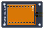 MH-RD
MH-RDThe Rain Sensor Pad is essentially a large, un-coated printed circuit board. It features two interlaced conductive tracks that do not touch. When water droplets (which are slightly conductive) fall on the board, they bridge the gap between the traces, lowering the overall resistance. This pad is designed to be connected to the Raindrop Module (LM393) to read the moisture levels.
Overview
Because this is a passive component acting as a variable resistor, it has no defined polarity (no Anode or Cathode). You simply connect its two pins to the corresponding two input header pins on the LM393 Raindrop Module.
Pin Reference
| Pin | Type | Description |
|---|---|---|
| Pin 1 | passive | Leg 1. Connects to the Raindrop Module. |
| Pin 2 | passive | Leg 2. Connects to the Raindrop Module. |
Configurable Attributes
(Note: In the simulator, the Rain Sensor Pad is typically just a visual representation. The actual moisture simulation is configured on the Raindrop Module itself via the rainLevel or threshold.)
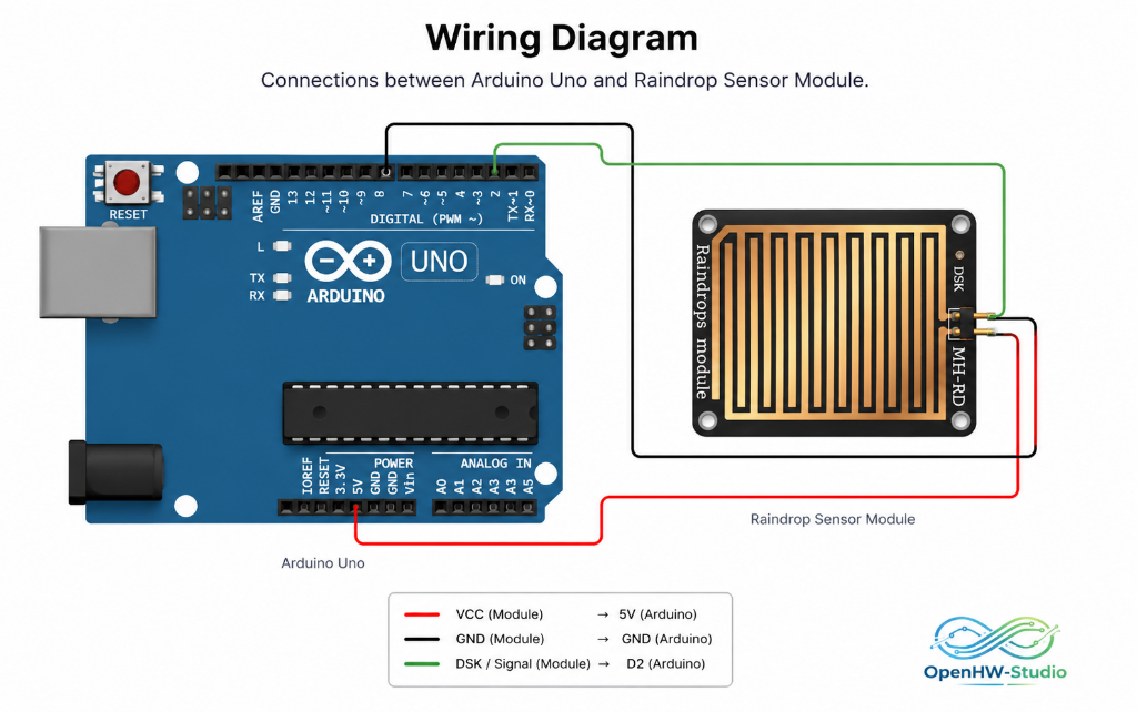
Wiring Diagram (Arduino Uno)
To use the pad, it must be paired with the LM393 Raindrop Module.
- Connect Pin 1 of the Pad to the top-left pin of the Raindrop Module.
- Connect Pin 2 of the Pad to the top-right pin of the Raindrop Module.
- Wire the Raindrop Module to the Arduino as shown.
Example Arduino Code
(See the Raindrop Module page for the full code example, as the Arduino interfaces directly with the module, not the pad).
Simulation Notes
- In OpenHW Studio, place this pad alongside the Raindrop Module to represent the complete hardware setup visually.
- To simulate rain, interact directly with the Raindrop Module UI element.