
nRF24L01+ Transceiver
A low-cost, highly integrated 2.4GHz ISM band RF transceiver module for establishing wireless networks between Arduinos.
Component Preview
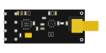 nRF24L01+
The nRF24L01+ operates in the 2.4GHz worldwide ISM frequency band. It supports up to 6 channels of data reception ("pipes"), allowing for star networks. It communicates with the Arduino over SPI.
Overview
Because it uses the 2.4GHz band (like Wi-Fi and Bluetooth), the nRF24L01+ can transmit data at high speeds (up to 2 Mbps) over short distances, making it ideal for remote control cars, wireless sensor networks, and smart home devices.
CAUTION
Voltage Warning: The nRF24L01+ module requires 3.3V power. Connecting its VCC pin to 5V will permanently damage the chip! (The logic pins are 5V tolerant, but the power pin is strictly 3.3V).
Pin Reference
| Pin | Type | Description |
|---|---|---|
| GND | power | Ground. Connect to Arduino GND. |
| VCC | power | 3.3V Power Supply. (DO NOT CONNECT TO 5V). |
| CE | digital | Chip Enable. Used to activate RX or TX mode. Connect to Arduino D7 (or any digital pin). |
| CSN | digital | SPI Chip Select. Connect to Arduino D8 (or any digital pin). |
| SCK | digital | SPI Clock. Connect to Arduino D13. |
| MOSI | digital | SPI Master Out Slave In. Connect to Arduino D11. |
| MISO | digital | SPI Master In Slave Out. Connect to Arduino D12. |
| IRQ | digital | Interrupt Request. Can optionally trigger when data is sent/received. |
Configurable Attributes
| Attribute | Type | Default | Description |
|---|---|---|---|
| magicInterop | boolean | false | When enabled in the simulator, allows automatic bridging of data streams without configuring exact pipe addresses. |
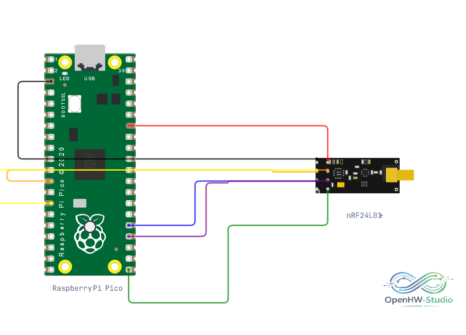
Wiring Diagram (Raspberry Pi Pico)
Example of wiring the nRF24L01+ module to a microcontroller using hardware SPI.
Example Arduino Code
Install the RF24 library by TMRh20 before running. This example sets up a simple transmitter.
#include <SPI.h>
#include <nRF24L01.h>
#include <RF24.h>

// CE, CSN pins
RF24 radio(7, 8);
const byte address[6] = "00001";

void setup() {
  Serial.begin(9600);

  if (!radio.begin()) {
    Serial.println("nRF24L01 not responding!");
    while (1);
  }

  // Set the address we are transmitting to
  radio.openWritingPipe(address);

  // Set the PA Level low for testing close together
  radio.setPALevel(RF24_PA_MIN);

  // Set the module as transmitter
  radio.stopListening();

  Serial.println("nRF24 Transmitter Ready.");
}

void loop() {
  const char text[] = "Hello World";

  // Send data
  if (radio.write(&text, sizeof(text))) {
    Serial.println("Message Sent successfully.");
  } else {
    Serial.println("Message Failed.");
  }

  delay(1000);
}
Simulation Notes
- In the OpenHW Simulator, you need at least two Arduinos (each with an nRF24L01+) to demonstrate communication. One must be set as a transmitter (
stopListening) and the other as a receiver (startListening). - Ensure both modules are configured to the same pipe address.