
ESP32-CAM
A highly integrated, ultra-small IoT camera module based on the ESP32.
Component Preview
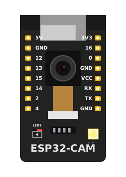 AI-Thinker ESP32-CAM
The ESP32-CAM is a tiny camera module featuring the ESP32-S chip alongside an OV2640 camera and an onboard TF (microSD) card slot. It's incredibly popular for building wireless security cameras, smart doorbells, face recognition systems, and machine learning vision projects. It also features a bright onboard LED flash.
Overview
Because the camera and microSD card slot monopolize many of the ESP32's internal GPIO pins, the ESP32-CAM breaks out far fewer user-accessible pins than a standard ESP32 development board. It also lacks a built-in USB-to-Serial converter, meaning you must use an FTDI programmer (connected to the RX, TX, and GND pins) and temporarily jump pin IO0 to GND to upload code.
WARNING
Power Requirements: The ESP32-CAM is notorious for power brownouts, particularly when initializing the Wi-Fi radio and camera sensor simultaneously. Ensure you provide a robust 5V power supply (at least 2 Amps) to the 5V pin.
Pin Reference
| Pin | Type | Description |
|---|---|---|
| 5V | power | 5V Power Input (Recommended over 3.3V to prevent brownouts). |
| 3V3 | power | 3.3V Power Input / Output. |
| GND | power | Common Ground (There are 3 GND pins available). |
| IO0 (0) | digital | Strapping pin. Must be connected to GND during boot to enter flashing mode. |
| U0R (RX) | digital | UART Receive. Connects to FTDI TX for programming. |
| U0T (TX) | digital | UART Transmit. Connects to FTDI RX for programming. |
| IO4 (4) | digital | Connected internally to the bright Flash LED. |
| IO33 (Internal) | digital | Not broken out. Connected internally to the small red status LED on the back. |
| IO12, IO13, IO14, IO15, IO2, IO16 | digital | General purpose I/O, but note that many are shared with the SD card interface. |
Configurable Attributes
(Currently, microcontroller boards in the simulator do not have configurable graphical attributes. You upload code to them directly via the editor.)
Wiring Diagram (Flash LED Control)
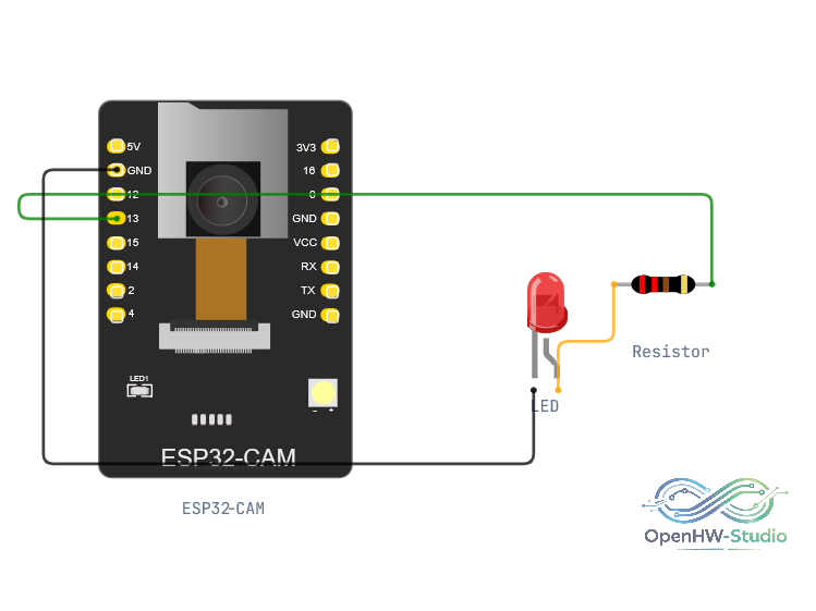
A simple setup demonstrating that you can use the ESP32-CAM to drive external components while maintaining standard Wi-Fi operations. Here, an external LED is connected to IO12. Note the bright internal Flash LED is mapped to IO4.
- Connect a 220-ohm resistor to pin 12.
- Connect the other end of the resistor to the Anode of an LED.
- Connect the Cathode of the LED to GND.
Example Code (Blinking the Flash LED)
This code demonstrates how to control the ultra-bright onboard flash LED (connected to IO4). Be careful, it is very bright!
// The flash LED is connected to GPIO 4
const int flashLedPin = 4;

void setup() {
  pinMode(flashLedPin, OUTPUT);
  Serial.begin(115200);
}

void loop() {
  Serial.println("Flash ON");
  // Turn the flash LED on
  digitalWrite(flashLedPin, HIGH);
  delay(200); // Only leave it on briefly!

  Serial.println("Flash OFF");
  // Turn the flash LED off
  digitalWrite(flashLedPin, LOW);
  delay(2000);
}
Simulation Notes
- The OpenHW Studio simulator currently provides a simulated "dummy" camera feed for testing basic image capture and streaming scripts.
- To program the ESP32-CAM in reality, you need an external USB-to-Serial adapter. In the simulator, this flashing step is handled virtually and instantly when you press "Upload".
- In the simulator environment,
IO4is fully modeled and will illuminate the graphical flash LED component on the board SVG.