
Motor Driver (L298N)
A robust dual H-bridge motor driver capable of controlling the speed and direction of two DC motors simultaneously.
Component Preview
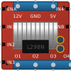 L298N Module
The L298N is a high-current dual H-bridge motor driver. It allows an Arduino (which can only output tiny amounts of current) to control the heavy current required to drive two DC motors or one bipolar stepper motor in both forward and reverse directions.
Overview
Because microcontrollers cannot provide enough current to drive motors directly, you must use a driver. The L298N acts as a heavy-duty switch, toggling the motor power supply on and off based on low-current signals from the Arduino. It also supports PWM input to control motor speed.
Pin Reference
| Pin | Type | Description |
|---|---|---|
| ENA | digital | Enable A. Connect to a PWM pin to control the speed of Motor A. |
| IN1 | digital | Input 1 for Motor A direction control. |
| IN2 | digital | Input 2 for Motor A direction control. |
| IN3 | digital | Input 3 for Motor B direction control. |
| IN4 | digital | Input 4 for Motor B direction control. |
| ENB | digital | Enable B. Connect to a PWM pin to control the speed of Motor B. |
| OUT1 | power | Motor A output terminal 1. |
| OUT2 | power | Motor A output terminal 2. |
| OUT3 | power | Motor B output terminal 1. |
| OUT4 | power | Motor B output terminal 2. |
| 12V | power | External motor power supply (typically 6V to 12V). |
| GND | power | Ground. Connect to external battery GND and Arduino GND. |
| 5V | power | 5V Out. Can be used to power the Arduino if the 12V supply is active. |
Configurable Attributes
This component has no standard configurable attributes.
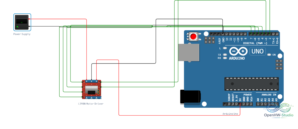
Wiring Diagram (Single Motor)
This diagram shows how to wire a single DC motor to the L298N.
Example Arduino Code
This code accelerates a DC Motor on channel A forward, stops it, and runs it in reverse.
// Motor A connections
int enA = 9;
int in1 = 8;
int in2 = 7;

void setup() {
  // Set all the motor control pins to outputs
  pinMode(enA, OUTPUT);
  pinMode(in1, OUTPUT);
  pinMode(in2, OUTPUT);

  // Turn off motor initially
  digitalWrite(in1, LOW);
  digitalWrite(in2, LOW);
}

void loop() {
  // Set Motor A forward
  digitalWrite(in1, HIGH);
  digitalWrite(in2, LOW);

  // Set speed out of possible range 0~255
  analogWrite(enA, 200);
  delay(2000);

  // Stop the motor
  digitalWrite(in1, LOW);
  digitalWrite(in2, LOW);
  delay(1000);

  // Set Motor A reverse
  digitalWrite(in1, LOW);
  digitalWrite(in2, HIGH);

  // Set speed
  analogWrite(enA, 200);
  delay(2000);

  // Stop again
  digitalWrite(in1, LOW);
  digitalWrite(in2, LOW);
  delay(1000);
}
Simulation Notes
- In the simulator, the physical rotation of attached DC motors will visually reflect the PWM duty cycle applied to
ENA/ENB. - It is critical to share a common GND between the Arduino and the L298N module.