
ESP32
A feature-rich, dual-core MCU equipped with Wi-Fi and dual-mode Bluetooth, ideal for IoT applications.
Component Preview
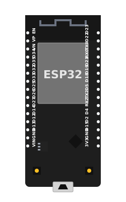 ESP32 Dev Module
The ESP32 is a low-cost, low-power system on a chip (SoC) microcontroller with integrated Wi-Fi and dual-mode Bluetooth. Developed by Espressif Systems, it boasts a dual-core Tensilica Xtensa LX6 microprocessor and is highly favored by makers and engineers for building robust Internet of Things (IoT) devices.
Overview
Unlike standard 8-bit AVR Arduinos, the ESP32 is a 32-bit microcontroller that operates at 3.3V. It offers an incredible array of peripherals, including capacitive touch, ADCs, DACs, I2C, SPI, UART, and I2S interfaces. Its internal Wi-Fi stack allows you to connect to the internet, host web servers, or fetch APIs directly from the microcontroller.
CAUTION
3.3V Logic Level: The ESP32 is not 5V-tolerant. Applying 5V to any of its GPIO pins can instantly damage the chip. Always use logic level converters when interfacing with 5V components.
Pin Reference
The ESP32 has many pins with overlapping capabilities. Most pins can be assigned to different hardware functions via software.
| Pin | Type | Description |
|---|---|---|
| 3V3 | power | Regulated 3.3V output. |
| VIN | power | Input voltage (typically 5V via USB or external supply). |
| GND | power | Ground pins. |
| EN | digital | Enable pin (Reset). Pulling this low resets the ESP32. |
| D0-D35 | digital | General Purpose I/O pins (GPIO). Most support PWM. |
| VP / VN | analog | Analog inputs (ADC1). Often labeled GPIO36 (VP) and GPIO39 (VN). Note: Input only. |
| TX0 / RX0 | digital | Hardware Serial 0 (used for USB programming/debugging). |
| TX2 / RX2 | digital | Hardware Serial 2. |
(Note: Pins D34, D35, VP(36), and VN(39) are input only and cannot be used as outputs or have internal pull-ups.)
Configurable Attributes
(Currently, microcontroller boards in the simulator do not have configurable graphical attributes. You upload code to them directly via the editor.)
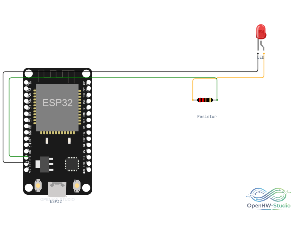
Wiring Diagram (Blink Example)
A standard setup to blink an external LED using the ESP32.
- Connect a 220-ohm resistor to pin D13.
- Connect the other end of the resistor to the Anode of an LED.
- Connect the Cathode of the LED to GND.
Example Code (Wi-Fi Scan)
This example demonstrates one of the ESP32's primary features: scanning for nearby Wi-Fi networks.
#include "WiFi.h"

void setup() {
  Serial.begin(115200);

  // Set WiFi to station mode and disconnect from an AP if it was previously connected
  WiFi.mode(WIFI_STA);
  WiFi.disconnect();
  delay(100);

  Serial.println("Setup done");
}

void loop() {
  Serial.println("scan start");

  // WiFi.scanNetworks will return the number of networks found
  int n = WiFi.scanNetworks();
  Serial.println("scan done");

  if (n == 0) {
      Serial.println("no networks found");
  } else {
    Serial.print(n);
    Serial.println(" networks found");
    for (int i = 0; i < n; ++i) {
      // Print SSID and RSSI for each network found
      Serial.print(i + 1);
      Serial.print(": ");
      Serial.print(WiFi.SSID(i));
      Serial.print(" (");
      Serial.print(WiFi.RSSI(i));
      Serial.println(")");
      delay(10);
    }
  }
  Serial.println("");

  // Wait a bit before scanning again
  delay(5000);
}
Simulation Notes
- In OpenHW Studio, ensure you select an "ESP32" board definition in the editor to use ESP32-specific libraries like
WiFi.h. - The simulator provides a virtual Wi-Fi environment, allowing code like
WiFi.scanNetworks()to function and return simulated access points. - Pay attention to the baud rate! The ESP32 standard debug baud rate is typically
115200, whereas standard Arduinos often default to9600.