
D Flip-Flop
A digital memory element that captures and stores a single bit of data on the rising edge of a clock signal.
Component Preview
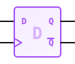 D Flip-Flop
The D (Data) Flip-Flop is the fundamental building block of digital memory. It tracks its input (D) and updates its output (Q) to match that input only when a rising clock edge is detected. It holds that value steady until the next rising clock edge.
Logic ComponentsSequential LogicMemory
Overview
D Flip-Flops are crucial for creating registers, shift registers, and finite state machines. Unlike combinational logic (AND, OR), the D Flip-Flop has "state" (memory) and relies on a synchronized clock signal to operate.
Pin Reference
| Pin | Type | Description |
|---|---|---|
| D | input | Data Input. The logic value (HIGH or LOW) to be stored. |
| CLK | input | Clock Input. The flip-flop captures the value of D on the rising edge (transition from LOW to HIGH) of this signal. |
| Q | digital | The current stored state. |
| Q' | digital | The inverted stored state (NOT Q). |
Configurable Attributes
This basic D Flip-Flop has no configurable attributes.
Working Principle
State Transition Table
| CLK (Edge) | D | Q (Next State) | Q' (Next State) |
|---|---|---|---|
↑ (Rising) | 0 | 0 | 1 |
↑ (Rising) | 1 | 1 | 0 |
0, 1, ↓ | X | No Change (Q) | No Change (Q') |
- Rising Edge: The moment the CLK pin transitions from LOW (0) to HIGH (1).
- Hold: At all other times (CLK is constant 0, constant 1, or falling from 1 to 0), changes on the D pin are ignored, and the outputs hold their current values.
Wiring Diagram
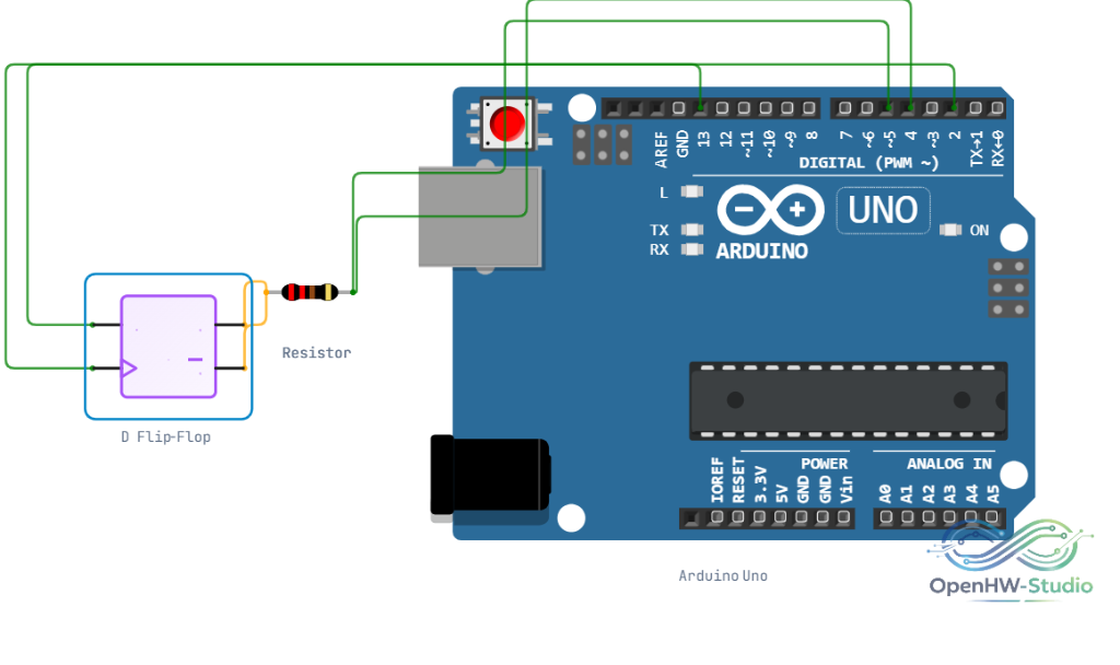
Example Arduino Code
You can emulate the behavior of a hardware D Flip-Flop in code, evaluating on rising edges.
cpp
const int pinD = 2;   // Data Input
const int pinCLK = 3; // Clock Input
const int pinQ = 4;   // State Output

bool lastClkState = LOW;
bool stateQ = LOW;

void setup() {
  pinMode(pinD, INPUT);
  pinMode(pinCLK, INPUT);
  pinMode(pinQ, OUTPUT);
}

void loop() {
  bool currentClkState = digitalRead(pinCLK);

  // Detect Rising Edge
  if (currentClkState == HIGH && lastClkState == LOW) {
    // Capture Data
    stateQ = digitalRead(pinD);
  }

  // Drive Output
  digitalWrite(pinQ, stateQ);

  lastClkState = currentClkState;
}
Simulation Notes
- The initial state of Q is LOW (0) by default upon starting the simulation.
- Ensure your clock signal is clean. In the simulator, the Clock Generator component provides a perfect signal. If using a push-button, be aware of switch bouncing if debouncing logic is not applied.
Notes / Warnings
- This is a standard Edge-Triggered D Flip-Flop without asynchronous Set or Reset pins. For Set/Reset capabilities, use the D Flip-Flop (SR) variant.