
RGB LED
A versatile 4-pin LED that combines three separate LEDs (Red, Green, Blue) into a single package to produce millions of colors.
Component Preview
 RGB LED
An RGB LED is essentially three separate LEDs housed in one bulb. By using PWM (Pulse Width Modulation) on the R, G, and B pins, you can independently adjust the brightness of each color channel, mixing them to create almost any color imaginable.
DisplaysLightPWM
Overview
RGB LEDs come in two internal wiring configurations:
- Common Cathode: All three internal LEDs share a single Ground pin (COM). You turn a color ON by sending a HIGH signal (or PWM) to its respective pin.
- Common Anode: All three internal LEDs share a single VCC/5V pin (COM). You turn a color ON by pulling its respective pin LOW.
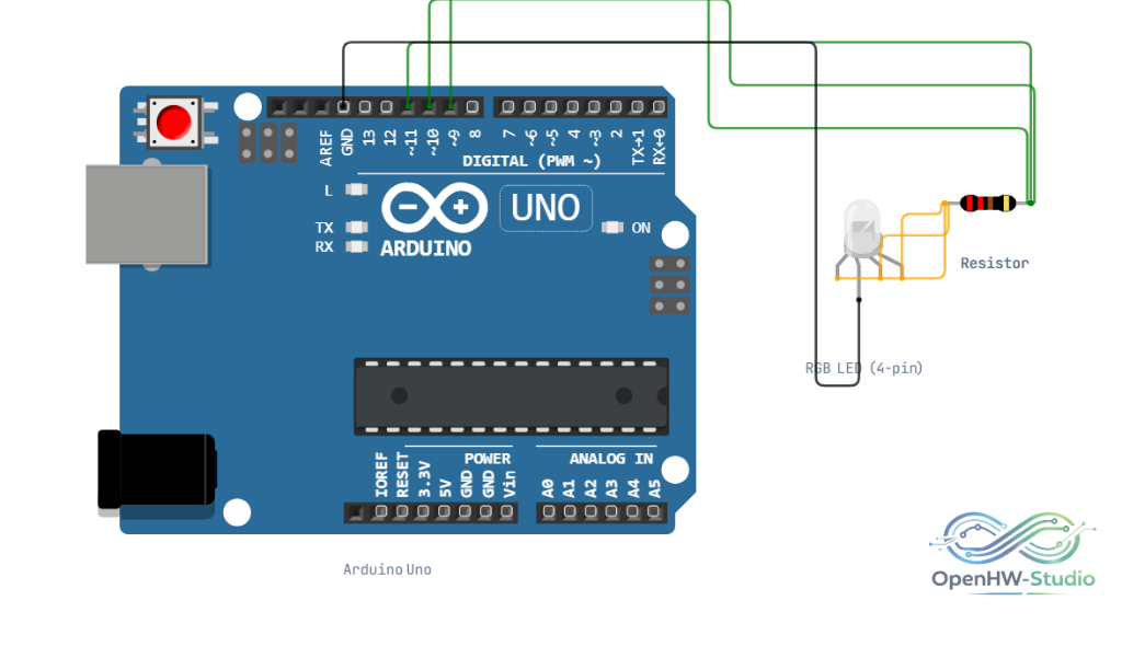
Note: You must use current-limiting resistors (usually 220Ω) on the R, G, and B pins, just like standard LEDs.
Pin Reference
| Pin | Type | Description |
|---|---|---|
| R | digital | Red channel. Connect to a PWM pin (with resistor). |
| COM | power | Common pin. Connect to GND (Cathode) or 5V (Anode). |
| G | digital | Green channel. Connect to a PWM pin (with resistor). |
| B | digital | Blue channel. Connect to a PWM pin (with resistor). |
Configurable Attributes
| Attribute | Type | Default | Description |
|---|---|---|---|
| common | string | "cathode" | Configuration of the common pin: "cathode" or "anode". |
Wiring Diagram
Connect the RGB LED to the Arduino using PWM pins to control colors.
Example Arduino Code
This code cycles through Red, Green, and Blue by writing PWM values (0-255) to a Common Cathode RGB LED.
cpp
#define PIN_R 9
#define PIN_G 10
#define PIN_B 11

void setup() {
  pinMode(PIN_R, OUTPUT);
  pinMode(PIN_G, OUTPUT);
  pinMode(PIN_B, OUTPUT);
}

void loop() {
  // Pure Red
  setColor(255, 0, 0);
  delay(1000);

  // Pure Green
  setColor(0, 255, 0);
  delay(1000);

  // Pure Blue
  setColor(0, 0, 255);
  delay(1000);

  // Yellow (Red + Green)
  setColor(255, 255, 0);
  delay(1000);
}

// Helper function to set the color
void setColor(int redValue, int greenValue, int blueValue) {
  analogWrite(PIN_R, redValue);
  analogWrite(PIN_G, greenValue);
  analogWrite(PIN_B, blueValue);
}
Simulation Notes
- The OpenHW Simulator fully supports PWM color mixing. Ensure you connect the R, G, and B pins to Arduino pins that have a
~symbol (like 3, 5, 6, 9, 10, 11 on the Uno) to useanalogWrite().