
DS1307 RTC Module
An I2C real-time clock (RTC) that maintains the current date and time even when the microcontroller is powered off.
Component Preview
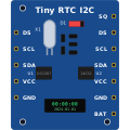 DS1307 RTC
The DS1307 maintains date and time data in BCD (Binary Coded Decimal) format. It communicates with microcontrollers using the I2C bus at address 0x68. The onboard CR2032 battery ensures the clock continues ticking even when main power is removed.
Overview
Microcontrollers like the Arduino do not inherently know the current time, and their internal millis() counter resets to 0 every time they lose power. The RTC module solves this by providing a permanent time reference.
Pin Reference
| Pin | Type | Description |
|---|---|---|
| VCC | power | Power supply. Connect to 5V. |
| GND | power | Ground. Connect to Arduino GND. |
| SDA | digital | I2C Data line. Connect to Arduino A4 (or SDA). |
| SCL | digital | I2C Clock line. Connect to Arduino A5 (or SCL). |
| SQ | digital | Optional square wave output (1Hz, 4kHz, 8kHz, 32kHz). |
Configurable Attributes
| Attribute | Type | Default | Description |
|---|---|---|---|
| datetime | string | 2024-01-01T00:00:00 | The starting date and time for the simulation clock. You can change this dynamically during simulation by right-clicking the module. |
| i2cAddress | string | 0x68 | Internal I2C address. Generally fixed at 0x68 for the DS1307. |
Working Principle
The DS1307 contains 64 bytes of NVRAM, the first 8 of which are reserved for timekeeping registers (Seconds, Minutes, Hours, Day, Date, Month, Year, Control). To read or write the time, you request specific register addresses over I2C.
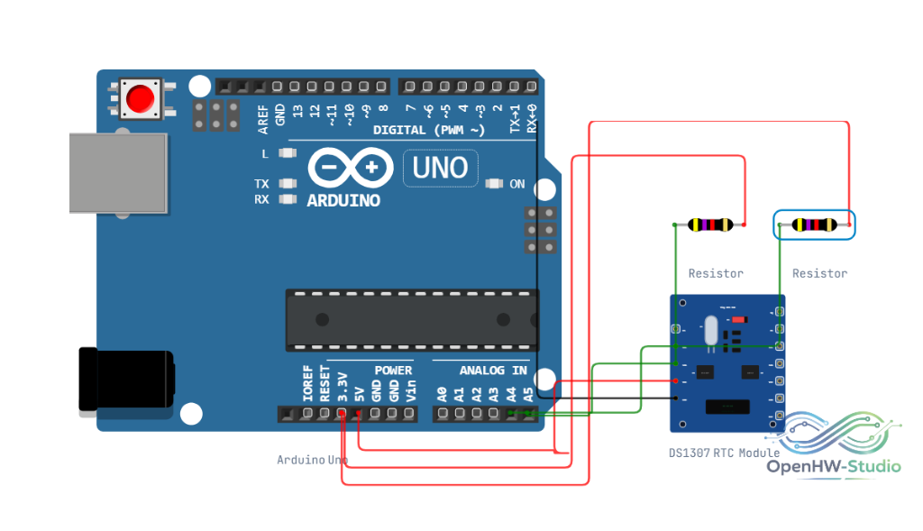
Wiring Diagram
- Connect VCC to 5V.
- Connect GND to GND.
- Connect SDA to Arduino analog pin A4.
- Connect SCL to Arduino analog pin A5.
Example Arduino Code
Install the RTClib library by Adafruit before running this code.
#include <Wire.h>
#include <RTClib.h>

RTC_DS1307 rtc;

void setup() {
  Serial.begin(9600);
  Wire.begin();

  if (!rtc.begin()) {
    Serial.println("Couldn't find RTC");
    while (1);
  }

  if (!rtc.isrunning()) {
    Serial.println("RTC is NOT running, let's set the time!");
    // Set the RTC to the date & time this sketch was compiled
    rtc.adjust(DateTime(F(__DATE__), F(__TIME__)));
  }
}

void loop() {
  DateTime now = rtc.now();

  Serial.print(now.year(), DEC);
  Serial.print('/');
  Serial.print(now.month(), DEC);
  Serial.print('/');
  Serial.print(now.day(), DEC);
  Serial.print(" ");
  Serial.print(now.hour(), DEC);
  Serial.print(':');
  Serial.print(now.minute(), DEC);
  Serial.print(':');
  Serial.print(now.second(), DEC);
  Serial.println();

  delay(1000);
}
Simulation Notes
- In OpenHW Studio, the DS1307 simulates its internal clock oscillator. The clock automatically ticks in real-time as long as the simulation is playing.
- If you stop and restart the simulation, the clock will reset to the value specified in the
datetimeattribute unless you write new values to it via I2C code.