
16-Channel Mux (HP4067)
A 16-channel analog/digital multiplexer/demultiplexer for massively expanding your microcontroller's I/O pins.
Component Preview
This module acts like a 16-way rotary switch. Using four digital control pins, you can connect the single common signal pin (SIG) to any one of the 16 channel pins (C0-C15). It works with both digital and analog signals.
Overview
If you run out of pins on your Arduino (especially analog inputs), the HP4067 allows you to read 16 analog sensors using only one analog pin and four digital pins. It operates bidirectionally, so it can also act as a demultiplexer (routing a single signal to 16 different destinations).
Pin Reference
| Pin | Type | Description |
|---|---|---|
| VCC | power | Power supply (2V to 6V). |
| GND | power | Common ground. |
| EN | digital | Enable pin. Active LOW (connect to GND to enable). |
| S0, S1, S2, S3 | digital | Control pins. These 4 bits form a binary number (0-15) to select a channel. |
| SIG | analog | The common signal pin. Connects internally to the selected C0-C15 pin. |
| C0 to C15 | analog | The 16 multiplexed channels. |
Configurable Attributes
This component has no configurable attributes.
Working Principle
The four select pins (S0, S1, S2, S3) are treated as a 4-bit binary number. S0 is the Least Significant Bit (LSB).
0000(All LOW) connectsSIGtoC0.0001(S0 HIGH) connectsSIGtoC1.1111(All HIGH) connectsSIGtoC15.
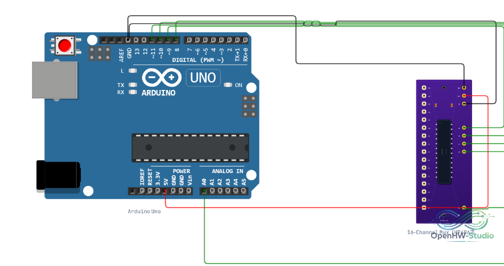
Wiring Diagram
Example of connecting the HP4067 16-Channel Mux to an Arduino Uno.
Example Arduino Code
This code loops through all 16 channels and reads their analog values.
// Define the selection pins
const int s0 = 2;
const int s1 = 3;
const int s2 = 4;
const int s3 = 5;

// Define the signal pin
const int sigPin = A0;

void setup() {
  Serial.begin(9600);
  pinMode(s0, OUTPUT);
  pinMode(s1, OUTPUT);
  pinMode(s2, OUTPUT);
  pinMode(s3, OUTPUT);
}

void loop() {
  // Loop through all 16 channels
  for (int channel = 0; channel < 16; channel++) {
    // Write the binary value to the selection pins
    digitalWrite(s0, bitRead(channel, 0));
    digitalWrite(s1, bitRead(channel, 1));
    digitalWrite(s2, bitRead(channel, 2));
    digitalWrite(s3, bitRead(channel, 3));

    // Give the mux a tiny bit of time to switch (optional but good practice)
    delayMicroseconds(10);

    // Read the value from the selected channel
    int val = analogRead(sigPin);

    Serial.print("Channel ");
    Serial.print(channel);
    Serial.print(": ");
    Serial.println(val);
  }

  Serial.println("---");
  delay(1000);
}
Simulation Notes
- In the simulator, the multiplexer accurately propagates analog voltages, PWM signals, and digital states bidirectionally between the
SIGpin and the actively selectedCchannel. - If
ENis driven HIGH, the multiplexer disconnectsSIGcompletely (high impedance state).