
LDR Sensor Module (4-pin)
A photoresistor module with an onboard LM393 comparator, providing both an analog brightness reading and a digital threshold trigger.
Component Preview
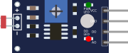 LDR Module
This module uses a Light Dependent Resistor (LDR). Its resistance decreases as light intensity increases. The onboard LM393 comparator compares the analog voltage against a potentiometer-set threshold, driving the Digital Output (DO) HIGH when it gets dark.
Overview
Unlike a bare photoresistor, this 4-pin module provides dual outputs. The Analog Output (AO) gives you a varying voltage that represents ambient light intensity, while the Digital Output (DO) acts as a simple day/night switch.
Pin Reference
| Pin | Type | Description |
|---|---|---|
| AO | analog | Analog Output. Outputs a voltage proportional to light intensity. Connect to A0. |
| DO | digital | Digital Output. Goes HIGH when light falls below the threshold. Connect to D4. |
| GND | power | Ground. Connect to Arduino GND. |
| VCC | power | Power Supply. Connect to Arduino 5V. |
Configurable Attributes
This component has no standard configurable attributes.
Working Principle
- Analog: A voltage divider is formed by the LDR and a fixed resistor. As light increases, LDR resistance drops, and
AOvoltage increases. - Digital: The LM393 chip compares
AOwith a reference voltage. WhenAOdrops below the reference (indicating it is dark), the comparator flipsDOto a HIGH state.
Wiring Diagram
- Connect VCC to 5V.
- Connect GND to GND.
- Connect AO to Arduino A0.
- Connect DO to Arduino D4.
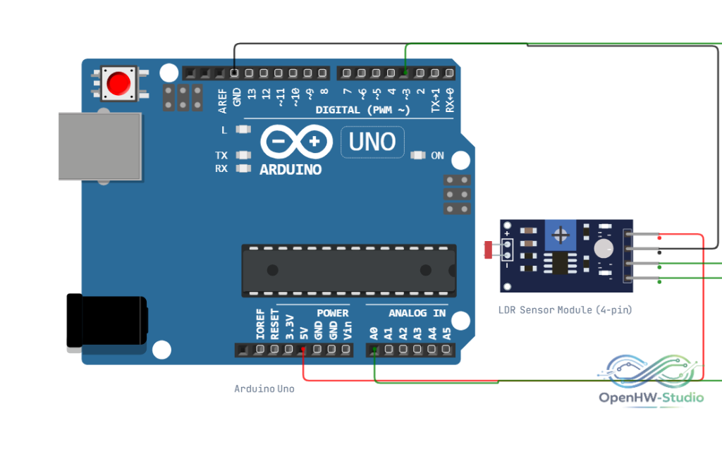
Example Arduino Code
This code reads both the analog light level and the digital threshold trigger simultaneously.
const int ldrDigitalPin = 4;
const int ldrAnalogPin = A0;

void setup() {
  Serial.begin(9600);
  pinMode(ldrDigitalPin, INPUT);
  Serial.println("LDR Sensor Ready");
}

void loop() {
  // Read both pins
  int analogVal = analogRead(ldrAnalogPin);
  int digitalVal = digitalRead(ldrDigitalPin);

  // Calculate a rough lux approximation (for simulation/demo purposes)
  float lux = (1023.0 - analogVal) / 1023.0 * 1000.0;

  Serial.print("Analog (0-1023): ");
  Serial.print(analogVal);
  Serial.print(" | Lux (Approx): ");
  Serial.print(lux, 0);

  // DO is HIGH when it is dark
  if (digitalVal == HIGH) {
    Serial.println(" | Status: DARK");
  } else {
    Serial.println(" | Status: LIGHT");
  }

  delay(500);
}
Simulation Notes
- In the simulator, clicking on the LDR module brings up an interactive "Lux" slider to simulate ambient light changing.
- Sliding it to the far left (0 Lux) will trigger the
DOpin to go HIGH.