
Push Button
A classic 12mm momentary tactile switch for providing digital input signals to the microcontroller.
Component Preview
 Tactile Button
A momentary tactile push button. When pressed, the circuit is closed, allowing current to flow between its terminals. When released, the connection is broken. It is fundamental for user interfaces and basic digital input.
Overview
Push buttons are fundamental input devices. This standard 4-pin tactile switch has two pairs of connected legs.
- Legs on the same side (e.g., Top Left and Top Right) are permanently connected internally.
- Legs across from each other (e.g., Top and Bottom) are disconnected until the button is pressed.
Pull-Up vs Pull-Down
To use a button reliably with a microcontroller, the input pin must not "float". It must be explicitly pulled HIGH or LOW when the button is not pressed.
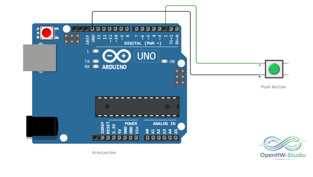
- Active-LOW (Recommended): Connect the button between the digital pin and Ground (GND). Enable the internal pull-up resistor using
pinMode(pin, INPUT_PULLUP). The pin readsHIGHwhen idle, andLOWwhen pressed. - Active-HIGH: Connect the button between the digital pin and 5V, and add a 10kΩ external pull-down resistor from the digital pin to Ground. The pin reads
LOWwhen idle, andHIGHwhen pressed.
Pin Reference
| Pin | Type | Description |
|---|---|---|
| 1L | passive | Terminal 1 Left. Connected to 1R internally. |
| 2L | passive | Terminal 2 Left. Connected to 2R internally. |
| 1R | passive | Terminal 1 Right. Connected to 1L internally. |
| 2R | passive | Terminal 2 Right. Connected to 2L internally. |
Configurable Attributes
| Attribute | Type | Default | Description |
|---|---|---|---|
| color | string | green | Visual button cap color (e.g., `red`, `blue`, `green`, `yellow`, `black`). |
Wiring Diagram
Example of connecting the Push Button (Active-LOW) to an Arduino Uno.
Example Arduino Code
This example demonstrates the recommended Active-LOW wiring using the internal pull-up resistor. No external resistors are required.
const int buttonPin = 2;

void setup() {
  Serial.begin(9600);

  // Enable internal pull-up resistor.
  // Pin will be HIGH when button is NOT pressed.
  pinMode(buttonPin, INPUT_PULLUP);

  Serial.println("Push Button Ready");
}

void loop() {
  // Read the button state
  int buttonState = digitalRead(buttonPin);

  // Since we use INPUT_PULLUP, LOW means the button is pressed
  if (buttonState == LOW) {
    Serial.println("Button is PRESSED!");
  } else {
    Serial.println("Button is released.");
  }

  delay(100);
}
Simulation Notes
- In the OpenHW Simulator, you can simply click the button on the canvas while the simulation is running to toggle the signal and observe the input behavior immediately.