
Motor Driver (L293D)
A dual H-bridge motor driver IC capable of driving two DC motors bidirectionally or one bipolar stepper motor.
Component Preview
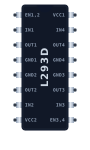 L293D IC
The L293D is an integrated circuit motor driver that can be used for simultaneous, bidirectional control of two DC motors. It contains two built-in H-bridges and internal flyback diodes to protect your microcontroller.
Overview
Microcontrollers like the Arduino cannot output enough current to drive motors directly. The L293D acts as an amplifier: it takes low-current control signals from the Arduino and uses them to switch a higher-current power supply dedicated to the motors.
Pin Reference
(Note: Pin numbering starts top-left at the notch and goes down, then up the right side).
| Pin | Type | Description |
|---|---|---|
| EN1,2 | digital | Enable pin for Motor 1. High = ON, Low = OFF. (PWM for speed control). |
| IN1 | digital | Input 1 for Motor 1 direction control. |
| OUT1 | digital | Output 1. Connect to motor 1 terminal A. |
| GND1/2 | power | Ground. Connect to Arduino GND and battery GND. |
| OUT2 | digital | Output 2. Connect to motor 1 terminal B. |
| IN2 | digital | Input 2 for Motor 1 direction control. |
| VCC2 | power | Motor Power (Vs). Connect to battery positive (up to 36V). |
| VCC1 | power | Logic Power (Vss). Connect to Arduino 5V. |
| IN4 | digital | Input 4 for Motor 2 direction control. |
| OUT4 | digital | Output 4. Connect to motor 2 terminal B. |
| GND3/4 | power | Ground. Connect to Arduino GND and battery GND. |
| OUT3 | digital | Output 3. Connect to motor 2 terminal A. |
| IN3 | digital | Input 3 for Motor 2 direction control. |
| EN3,4 | digital | Enable pin for Motor 2. (PWM for speed control). |
Configurable Attributes
This component has no standard configurable attributes.
Working Principle (H-Bridge)
An H-Bridge allows voltage to be applied across a load in either direction.
- If
IN1is HIGH andIN2is LOW, the motor spins Forward. - If
IN1is LOW andIN2is HIGH, the motor spins Backward. - If both are LOW, the motor stops.
- Applying a PWM signal to
EN1,2pulses the power rapidly, changing the motor's average speed.
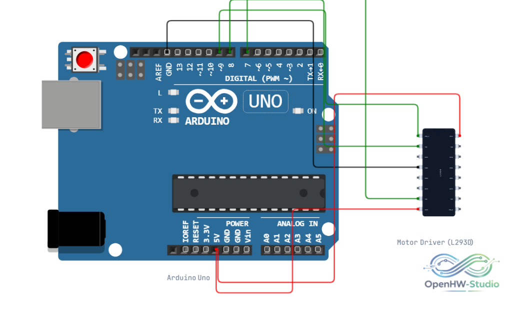
Wiring Diagram (Single Motor)
This diagram shows how to wire a single DC motor to the L293D.
Example Arduino Code
This code drives a single motor forward, then backward, then stops.
const int enA = 9;
const int in1 = 8;
const int in2 = 7;

void setup() {
  pinMode(enA, OUTPUT);
  pinMode(in1, OUTPUT);
  pinMode(in2, OUTPUT);
}

void loop() {
  // Full speed forward
  digitalWrite(in1, HIGH);
  digitalWrite(in2, LOW);
  analogWrite(enA, 255);
  delay(2000);

  // Full speed backward
  digitalWrite(in1, LOW);
  digitalWrite(in2, HIGH);
  analogWrite(enA, 255);
  delay(2000);

  // Stop
  digitalWrite(in1, LOW);
  digitalWrite(in2, LOW);
  delay(2000);
}
Simulation Notes
- The L293D perfectly simulates H-bridge logic. If you wire the VCC2 pin incorrectly, the motors will not spin.
- The motors in the simulation will display their RPM, allowing you to visually verify speed control via PWM.