
DC Motor
Converts electrical energy to rotational motion. Can be driven forwards or backwards depending on polarity.
Component Preview
 DC Motor
A DC motor converts electrical energy into rotational mechanical motion. The direction of spin is determined by current polarity across its terminals. It requires an H-bridge motor driver (e.g., L298N) for safe operation from an Arduino — never connect directly to an Arduino pin.
Overview
The DC Motor requires an external power source and a motor driver to be controlled by a microcontroller. It uses a simple two-wire connection. Depending on which wire is positive and which is negative, the motor will spin either forward or backward.
Pin Reference
| Pin | Type | Description |
|---|---|---|
| 1 | power | Motor Terminal 1 (usually Red wire). |
| 2 | power | Motor Terminal 2 (usually Black wire). |
Configurable Attributes
This component has no standard configurable attributes.
Wiring Diagram
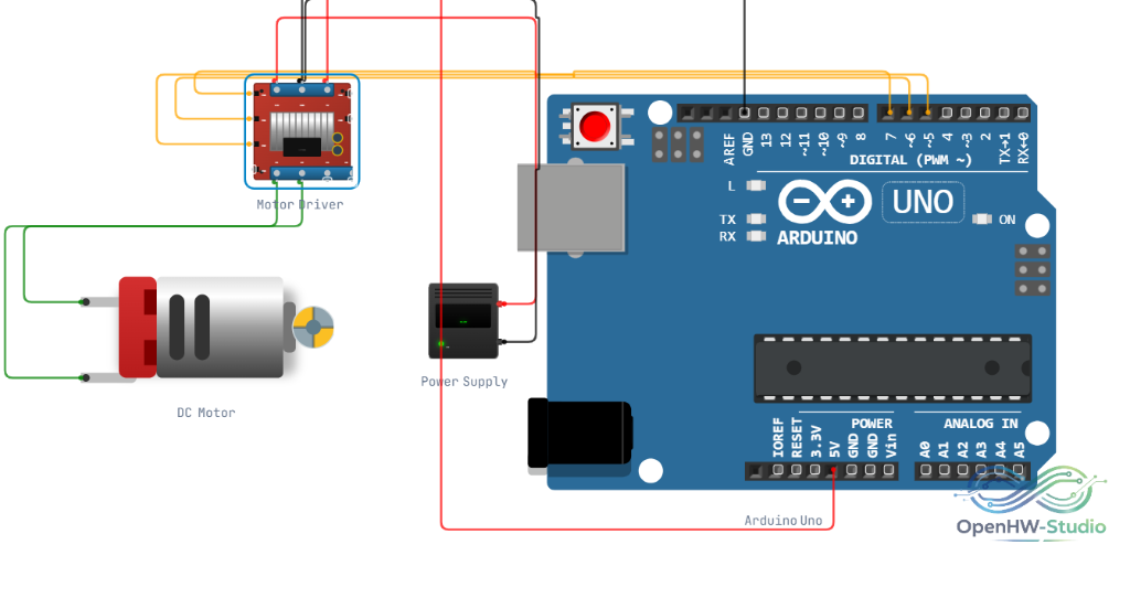
Typical wiring for a DC Motor using an L298N motor driver module with an Arduino Uno. Note that the OpenHW Simulator handles basic autowiring for this module.
TIP
Real Hardware Tip: Always add a flyback diode (e.g., 1N4007) across motor terminals to protect against inductive voltage spikes when building physical circuits.
Example Arduino Code
This basic sketch demonstrates how to control the DC motor's direction and speed using an L298N driver.
// Define driver pins
#define ENA 5   // PWM speed control
#define IN1 6   // Direction pin 1
#define IN2 7   // Direction pin 2

void setup() {
  // Set all motor control pins to outputs
  pinMode(ENA, OUTPUT);
  pinMode(IN1, OUTPUT);
  pinMode(IN2, OUTPUT);
}

void loop() {
  // Move Forward at 50% speed (128 out of 255)
  digitalWrite(IN1, HIGH);
  digitalWrite(IN2, LOW);
  analogWrite(ENA, 128);
  delay(2000);

  // Coast (Brake)
  digitalWrite(IN1, LOW);
  digitalWrite(IN2, LOW);
  analogWrite(ENA, 0);
  delay(1000);

  // Move Reverse at 100% speed
  digitalWrite(IN1, LOW);
  digitalWrite(IN2, HIGH);
  analogWrite(ENA, 255);
  delay(2000);

  // Coast (Brake)
  digitalWrite(IN1, LOW);
  digitalWrite(IN2, LOW);
  analogWrite(ENA, 0);
  delay(1000);
}
Simulation Notes
- The visual rotation of the motor shaft is proportional to the voltage applied across its terminals.