
7-Segment Display
A classic single-digit LED indicator used to display numerals and basic characters in retro electronics.
Component Preview
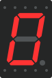 7-Segment
The 7-segment display is an arrangement of 7 distinct LEDs in a figure-8 pattern (plus a decimal point). By selectively turning on specific combinations of these segments, you can display any number from 0 to 9, as well as several alphabetical characters. It comes in Common Anode and Common Cathode variants.
DisplaysLEDNumerical
Overview
Before LCDs and OLEDs became ubiquitous, 7-segment displays were the primary way devices communicated numeric information to users. They are still widely used today due to their low cost, high visibility, and simplicity.
Pin Reference
| Pin | Type | Description |
|---|---|---|
| A | digital | Controls the top horizontal segment. |
| B | digital | Controls the top-right vertical segment. |
| C | digital | Controls the bottom-right vertical segment. |
| D | digital | Controls the bottom horizontal segment. |
| E | digital | Controls the bottom-left vertical segment. |
| F | digital | Controls the top-left vertical segment. |
| G | digital | Controls the middle horizontal segment. |
| DP | digital | Controls the Decimal Point (dot) at the bottom right. |
| COM.1 | power | Common pin (connects to VCC for Anode, GND for Cathode). |
| COM.2 | power | Second Common pin (internally connected to COM.1). |
Configurable Attributes
| Attribute | Type | Default | Description |
|---|---|---|---|
| color | string | "red" | The color of the illuminated segments. |
| common | string | "cathode" | Sets the display type. Use "anode" or "cathode". |
| digits | number | 1 | Number of digits (if multi-digit component is used). |
| colon | boolean | false | Enables a colon (:) between digits, usually for clocks. |
Working Principle
- Common Cathode: All 8 LEDs share a single Ground (
COM). To turn a segment ON, you supplyHIGHlogic to its respective pin (A-G). - Common Anode: All 8 LEDs share a single VCC (
COM). To turn a segment ON, you supplyLOWlogic to its respective pin, allowing current to sink into the microcontroller.
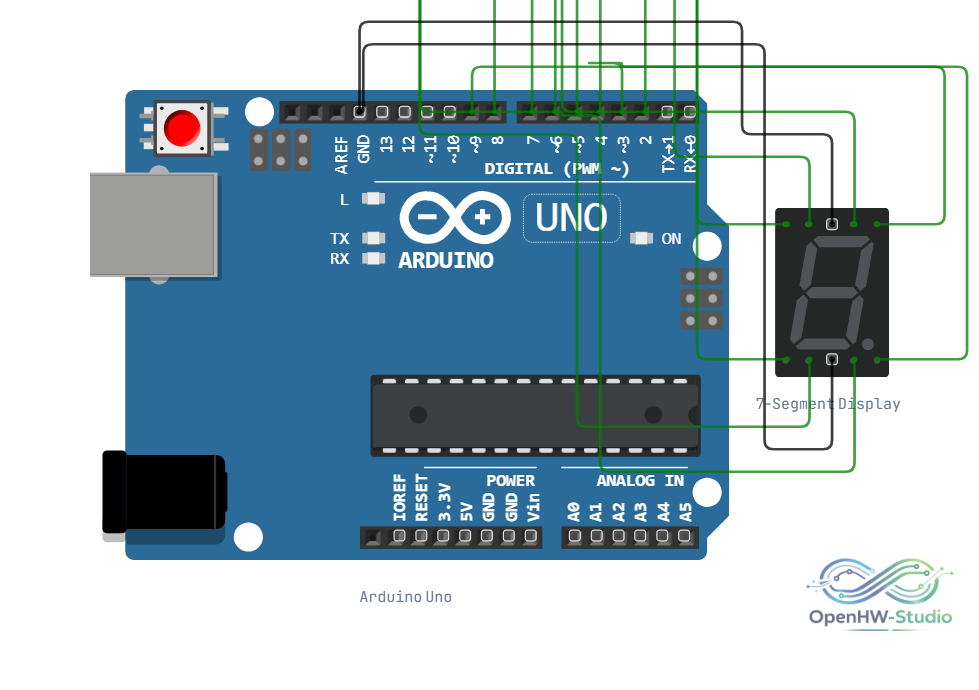
Wiring Diagram
Example Arduino Code
To simplify wiring and logic, the SevSeg library is highly recommended.
cpp
#include "SevSeg.h"
SevSeg sevseg;

void setup() {
  byte numDigits = 1;
  byte digitPins[] = {10}; // Connect COM to pin 10 if multiplexing, otherwise ignore
  // Pins in order: A, B, C, D, E, F, G, DP
  byte segmentPins[] = {2, 3, 4, 5, 6, 7, 8, 9};
  bool resistorsOnSegments = true;

  // Initialize as Common Cathode
  sevseg.begin(COMMON_CATHODE, numDigits, digitPins, segmentPins, resistorsOnSegments);
  sevseg.setBrightness(90);
}

void loop() {
  // Display the number 4
  sevseg.setNumber(4);
  sevseg.refreshDisplay(); // Must run repeatedly if multiplexing
}
Simulation Notes
- The simulator models both common anode and common cathode behaviors based on the
commonattribute. - Multi-digit displays use multiplexing, which requires rapid switching in the Arduino
loop(). If the simulation stutters, the display may appear to flicker just as it would in real life if the refresh rate is too low.