
Rotary Potentiometer
A classic adjustable resistor module that outputs a variable analog voltage.
Component Preview
 Rotary Potentiometer
A potentiometer is a three-terminal resistor with a sliding or rotating contact that forms an adjustable voltage divider. This module is pre-mounted on a breakout board with clearly labeled pins, making it incredibly easy to wire up to an Arduino for analog input reading, such as for volume control or adjusting motor speed.
Overview
Inside the potentiometer is a resistive track. The middle pin connects to a wiper that slides along this track when you turn the knob. By connecting the outer pins to Power and Ground, the wiper outputs a voltage proportional to its position, which can be read using analogRead().
Pin Reference
| Pin | Type | Description |
|---|---|---|
| GND | power | Ground. Connect to Arduino GND. |
| SIG | analog | Signal output. Connect to an analog input (e.g., A0). |
| VCC | power | Power input. Connect to Arduino 5V. |
Configurable Attributes
| Attribute | Type | Default | Description |
|---|---|---|---|
| value | number | 50 | The simulated knob position percentage (0-100). |
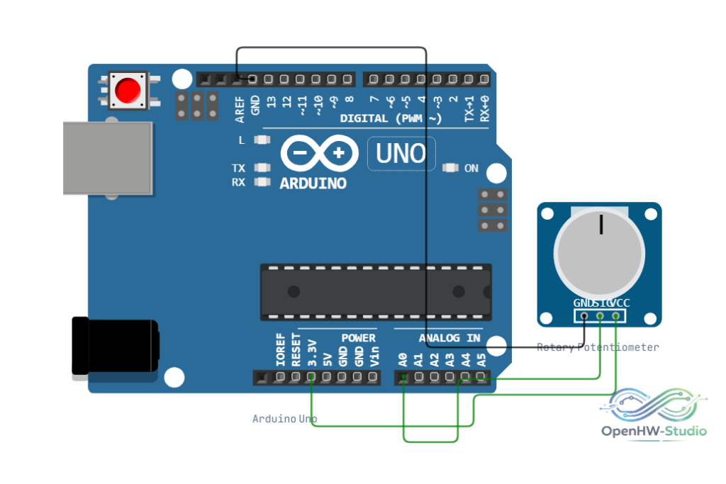
Wiring Diagram (Arduino Uno)
- Connect VCC to Arduino 5V.
- Connect GND to Arduino GND.
- Connect SIG to Arduino A0.
Example Arduino Code
This simple sketch reads the analog value from the potentiometer and prints it to the Serial Monitor.
const int potPin = A0;

void setup() {
  Serial.begin(9600);
}

void loop() {
  // Read the analog value (0-1023)
  int potValue = analogRead(potPin);

  // Calculate percentage
  int percentage = map(potValue, 0, 1023, 0, 100);

  Serial.print("Raw Value: ");
  Serial.print(potValue);
  Serial.print(" | Percentage: ");
  Serial.print(percentage);
  Serial.println("%");

  delay(100);
}
Simulation Notes
- In the simulator, click and drag the gray knob in a circular motion to adjust the value.
- A glowing yellow halo will appear when the knob is active.
- Turning the knob changes the simulated resistance instantly, updating the voltage on the
SIGpin.