
Raspberry Pi Pico W
The RP2040 microcontroller you love, now upgraded with fully certified 2.4GHz Wi-Fi capabilities.
Component Preview
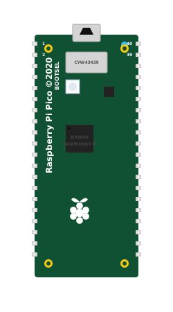 Raspberry Pi Pico W
The Raspberry Pi Pico W retains all the power and flexibility of the original Pico (including the RP2040 dual-core processor and PIO subsystem) but adds an Infineon CYW43439 wireless chip. This allows it to connect to 2.4GHz Wi-Fi networks, making it the perfect platform for IoT projects, smart home devices, and remote data logging.
Overview
Because the Pico W shares the exact same form factor and pinout as the original Pico, it is a drop-in replacement for existing hardware projects. The wireless chip is connected internally via SPI to the RP2040.
NOTE
Onboard LED Difference: On the standard Pico, the onboard LED is connected directly to GP25. On the Pico W, the onboard LED is connected to the WL_GPIO0 pin of the wireless chip. You must use specific wireless library functions (like cyw43_arch_gpio_put) to toggle the onboard LED.
Pin Reference
The Pico W has 40 pins configured in a dual in-line package (DIP) style, identical to the standard Pico.
| Pin Group | Description |
|---|---|
| GP0 - GP28 | 26 General Purpose I/O pins (3.3V logic only). All can be used for digital I/O and PWM. |
| ADC0 - ADC2 | 3 of the GPIO pins (GP26, GP27, GP28) have hardware Analog-to-Digital Converter capabilities. |
| VBUS | Micro-USB input voltage (typically 5V). Used for powering 5V peripherals. |
| VSYS | Main system input voltage (1.8V to 5.5V). Used to power the Pico from an external battery. |
| 3V3(OUT) | Regulated 3.3V output for powering external 3.3V sensors. |
| GND | Multiple ground pins distributed around the board. |
| RUN | Reset pin. Pulling this low resets the RP2040. |
Configurable Attributes
(Currently, microcontroller boards in the simulator do not have configurable graphical attributes. You upload code to them directly via the editor.)
Wiring Diagram (Blink Example)
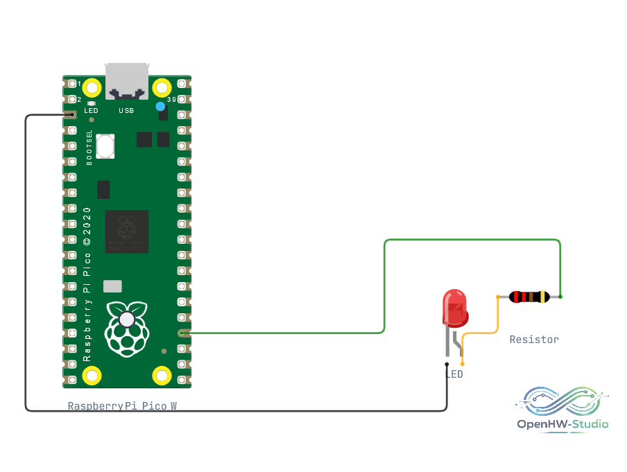
A typical configuration for testing digital output. Note that the layout is identical to the standard Pico.
- Connect a 220-ohm resistor to pin 18.
- Connect the other end of the resistor to the Anode of an LED.
- Connect the Cathode of the LED to GND.
Example Code
This code demonstrates a standard LED blink routine. In OpenHW Studio's autocoding blocks, the board's setup configuration defines 18 as the target for led_1.
void setup() {
  // autocoding for led_1 start
  pinMode(18, OUTPUT);
  // autocoding for led_1 end

  // put your setup code here, to run once:
}

void loop() {
  // autocoding for led_1 start
  digitalWrite(18, HIGH);
  delay(1000);
  digitalWrite(18, LOW);
  delay(1000);
  // autocoding for led_1 end

  // put your main code here, to run repeatedly:
}
Simulation Notes
- The OpenHW Studio simulator provides a virtual Wi-Fi environment for the Pico W. However, you must use the appropriate Pico W SDK or Arduino Core libraries to interact with the simulated wireless chip.
- Standard digital I/O, PWM, and I2C/SPI functions work identically to the standard Raspberry Pi Pico.