
SPI LED Driver (NLSF595)
A shift register similar to the 74HC595 but optimized with higher current capabilities for driving multiple LEDs directly without external transistors.
Component Preview
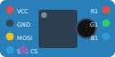 DIP-16 IC
The NLSF595 takes serial data in (via SPI or bit-banging) and outputs it in parallel across 8 pins. Unlike standard logic shift registers, it is designed to sink higher currents, making it ideal for directly driving LEDs or 7-segment displays.
Overview
Shift registers allow you to expand the number of output pins on your microcontroller. By using just 3 pins (Data, Clock, and Latch), you can control 8 outputs. Multiple NLSF595 chips can be daisy-chained together to control 16, 24, or more LEDs with those same 3 pins.
Pin Reference
(Note: As this represents a generic NLSF595 breakout module, the pinout is simplified compared to the raw IC).
| Pin | Type | Description |
|---|---|---|
| VCC | power | Power Supply (5V). |
| GND | power | Ground. |
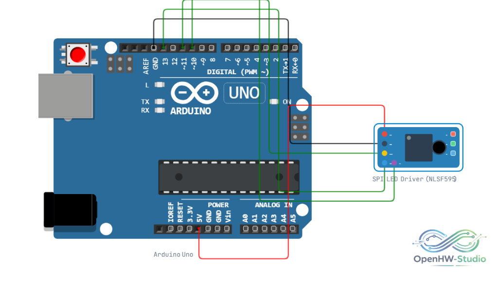
| MOSI | digital | Serial Data In (connect to Arduino D11 for hardware SPI, or any digital pin for shiftOut). |
| SCK | digital | Serial Clock (connect to Arduino D13 for hardware SPI, or any digital pin for shiftOut). |
| CS | digital | Chip Select / Latch (connect to Arduino D10 or any digital pin). |
| R1 | output | Example output pin for Red LED. |
| G1 | output | Example output pin for Green LED. |
| B1 | output | Example output pin for Blue LED. |
Configurable Attributes
This component has no standard configurable attributes.
Wiring Diagram
Connect the NLSF595 module to the Arduino via SPI pins.
Example Arduino Code
This code uses the built-in shiftOut() function to send an 8-bit value to the shift register. The latch pin must be pulled LOW before shifting data and pulled HIGH to update the outputs.
const int latchPin = 10;
const int dataPin = 11;
const int clockPin = 13;

void setup() {
  pinMode(latchPin, OUTPUT);
  pinMode(clockPin, OUTPUT);
  pinMode(dataPin, OUTPUT);
}

void loop() {
  // Turn all outputs ON (Binary 11111111 = 255)
  digitalWrite(latchPin, LOW);
  shiftOut(dataPin, clockPin, MSBFIRST, 255);
  digitalWrite(latchPin, HIGH);

  delay(1000);

  // Turn all outputs OFF (Binary 00000000 = 0)
  digitalWrite(latchPin, LOW);
  shiftOut(dataPin, clockPin, MSBFIRST, 0);
  digitalWrite(latchPin, HIGH);

  delay(1000);
}
Simulation Notes
- The OpenHW Simulator treats the NLSF595 identically to the 74HC595 for logic simulation purposes. It will output logic HIGH/LOW based on the shifted data.