
Li-ion Charger Module
A complete constant-current/constant-voltage linear charger for single-cell lithium-ion batteries.
Component Preview
 TP4056 Module
This module typically uses the TP4056 chip to safely charge a standard 3.7V Li-ion or Li-Po battery. It takes 5V power (either from a USB input or direct wire) and carefully manages the charging curve up to a maximum of 4.2V, cutting off automatically when full.
Overview
Rechargeable batteries require precise charging curves to prevent overheating or explosion. You cannot simply attach 5V to a Li-ion battery. This module acts as the middleman to handle the complex charging logic safely.
Pin Reference
| Pin | Type | Description |
|---|---|---|
| IN+ | power | Power input. Connect to a 5V source (like a solar panel or wall adapter). |
| IN- | power | Ground input. Connect to the power source ground. |
| BAT+ | power | Battery positive terminal. Connect to the VCC pin of a Li-ion Battery component. |
| B- | power | Connects to the negative terminal of the Li-ion battery. |
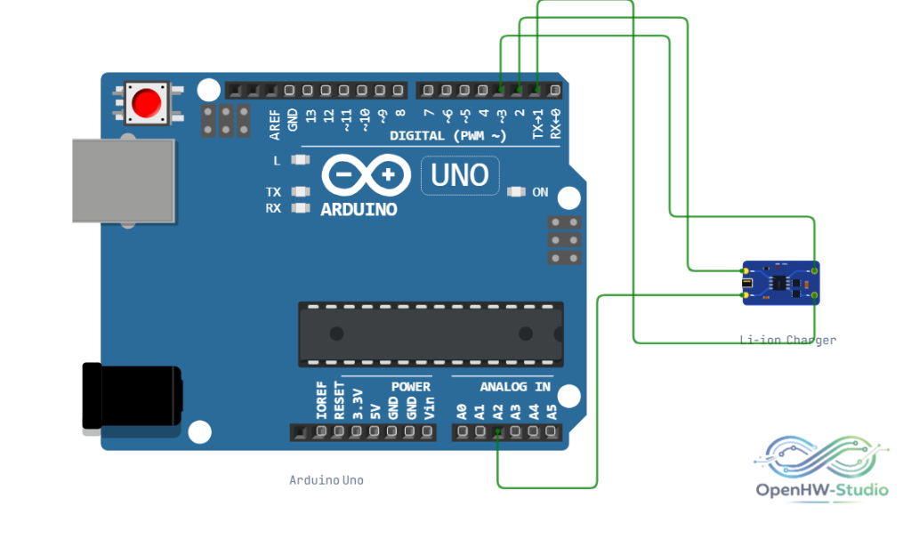
Wiring Diagram
Configurable Attributes
| Attribute | Type | Default | Description |
|---|---|---|---|
| chargeCurrentMa | number | 1000 | The simulated charging rate in mA. Defaults to 1A (1000mA). |
Working Principle
In the simulator, when 5V is applied to IN+/IN-, the module will output a charging voltage to BAT+/BAT-. If connected to a simulated Li-ion battery, the battery's currentChargeMah will steadily increase over time based on the chargeCurrentMa rate, until it reaches its maximum capacity.
Wiring Diagram
- Connect a 5V power source (e.g., from a simulated wall adapter or generator) to
IN+andIN-. - Connect a simulated Li-ion Battery to
BAT+andBAT-. - If the battery supports a load (like an ESP32), connect the ESP32 directly to the battery in parallel with the charger.
Example Arduino Code
The charger is entirely self-contained and operates purely via hardware physics. It does not require code to run.
If you wish to monitor it using an Arduino, you can read the battery voltage via an analog pin:
const int monitorPin = A0;

void setup() {
  Serial.begin(9600);
}

void loop() {
  // Simple voltage divider assuming 5V logic
  float voltage = analogRead(monitorPin) * (5.0 / 1023.0);

  if (voltage > 4.15) {
    Serial.println("Battery Fully Charged!");
  } else if (voltage < 3.2) {
    Serial.println("Battery Low!");
  } else {
    Serial.println("Battery Charging...");
  }

  delay(2000);
}
Simulation Notes
- The physical module often features red (charging) and green/blue (full) LEDs. In the simulator, the module tracks the battery state and updates its visual LEDs appropriately.