
ADXL345 Accelerometer
A precise 3-axis digital accelerometer used to measure static acceleration of gravity in tilt-sensing applications, as well as dynamic acceleration resulting from motion or shock.
Component Preview
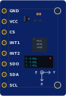 ADXL345 Module
The ADXL345 is a popular digital accelerometer module. It communicates via I2C or SPI and provides highly accurate readings of acceleration across the X, Y, and Z axes. It is commonly used for step counting, tilt sensing in robotics, and game controllers.
Overview
An accelerometer measures proper acceleration ("g-force"). Even when sitting completely still, the sensor will read roughly 1g (9.8 m/s²) straight down on the Z axis due to Earth's gravity. By analyzing the distribution of this 1g across the 3 axes, you can mathematically determine the module's exact orientation and tilt.
Pin Reference
| Pin | Type | Description |
|---|---|---|
| VCC | power | Power supply (Typically 3.3V, but many modules have a 5V regulator). |
| GND | power | Ground reference. |
| SCL | input | Serial Clock (I2C SCL or SPI SCLK). |
| SDA | digital | Serial Data (I2C SDA or SPI MOSI). |
| SDO | digital | Serial Data Out (SPI MISO) / I2C Address Select (ALT ADDRESS). |
| CS | input | Chip Select. Tie HIGH for I2C, use as standard CS for SPI. |
| INT1 | output | Programmable Interrupt 1 (e.g., tap detection, free-fall). |
| INT2 | output | Programmable Interrupt 2. |
Configurable Attributes
| Attribute | Type | Default | Description |
|---|---|---|---|
| accelX | number | 0 | Simulated acceleration on the X axis (in m/s²). |
| accelY | number | 0 | Simulated acceleration on the Y axis (in m/s²). |
| accelZ | number | 9.8 | Simulated acceleration on the Z axis (in m/s²). Default is 1g for gravity. |
Working Principle
Inside the silicon chip is a microscopic MEMS (Micro-Electro-Mechanical System) structure. A tiny mass is suspended by springs. When acceleration occurs, the mass shifts, changing the capacitance between it and fixed plates. This change is converted into a digital 13-bit value and sent over I2C/SPI.
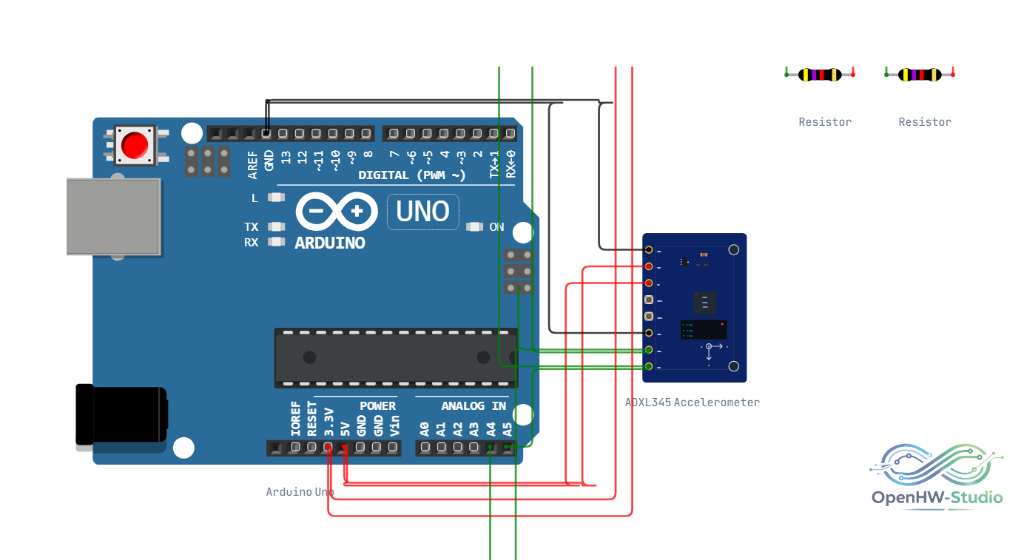
Wiring Diagram (I2C Mode)
- Connect VCC to 3.3V (or 5V if the module supports it).
- Connect GND to Ground.
- Connect SCL to the Arduino's SCL pin (A5 on Uno).
- Connect SDA to the Arduino's SDA pin (A4 on Uno).
- Tie CS to VCC to select I2C mode.
- Connect SDO to Ground to set the I2C address to
0x53. (Connecting to VCC sets it to0x1D).
Example Arduino Code
We highly recommend using the Adafruit Unified Sensor Library to handle the complex math required to convert raw data into standard SI units.
#include <Wire.h>
#include <Adafruit_Sensor.h>
#include <Adafruit_ADXL345_U.h>

/* Assign a unique ID to this sensor at the same time */
Adafruit_ADXL345_Unified accel = Adafruit_ADXL345_Unified(12345);

void setup() {
  Serial.begin(9600);
  Serial.println("Accelerometer Test");

  if(!accel.begin()) {
    Serial.println("No ADXL345 detected, check your wiring!");
    while(1);
  }

  accel.setRange(ADXL345_RANGE_16_G);
}

void loop() {
  sensors_event_t event;
  accel.getEvent(&event);

  // Display the results (acceleration is measured in m/s^2)
  Serial.print("X: "); Serial.print(event.acceleration.x); Serial.print("  ");
  Serial.print("Y: "); Serial.print(event.acceleration.y); Serial.print("  ");
  Serial.print("Z: "); Serial.print(event.acceleration.z); Serial.print("  ");
  Serial.println("m/s^2 ");

  delay(500);
}
Simulation Notes
- In the simulator, the module operates in I2C mode by default at address
0x53. - You can manually set the X, Y, and Z acceleration variables via the part attributes to test your code's tilt/motion logic without physically moving the device.