
Raspberry Pi Pico
The first microcontroller board from Raspberry Pi, powered by their custom RP2040 silicon.
Component Preview
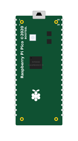 Raspberry Pi Pico (RP2040)
The Raspberry Pi Pico is a flexible, low-cost microcontroller board built around the RP2040 chip designed by Raspberry Pi. It features a dual-core Arm Cortex-M0+ processor, 264KB of internal RAM, and support for up to 16MB of off-chip flash. It is designed to be easily programmable via C/C++ or MicroPython.
Overview
Operating at 3.3V logic levels, the Pico offers a rich set of I/O options including 26 multi-function GPIO pins. It stands out with its unique Programmable I/O (PIO) subsystem, allowing you to create custom hardware interfaces. It features a micro-USB port for power and data, and a physical BOOTSEL button used for programming.
CAUTION
3.3V Logic Level: The Raspberry Pi Pico operates strictly at 3.3V. Providing 5V to any GPIO pin (other than VBUS) will damage the RP2040 chip. Use logic level shifters when connecting 5V components.
Pin Reference
The Pico has 40 pins configured in a dual in-line package (DIP) style.
| Pin Group | Description |
|---|---|
| GP0 - GP28 | 26 General Purpose I/O pins (3.3V logic only). All can be used for digital I/O and PWM. |
| ADC0 - ADC2 | 3 of the GPIO pins (GP26, GP27, GP28) have hardware Analog-to-Digital Converter capabilities. |
| VBUS | Micro-USB input voltage (typically 5V). Used for powering 5V peripherals. |
| VSYS | Main system input voltage (1.8V to 5.5V). Used to power the Pico from an external battery. |
| 3V3(OUT) | Regulated 3.3V output for powering external 3.3V sensors. |
| GND | Multiple ground pins distributed around the board. |
| RUN | Reset pin. Pulling this low resets the RP2040. |
Configurable Attributes
(Currently, microcontroller boards in the simulator do not have configurable graphical attributes. You upload code to them directly via the editor.)
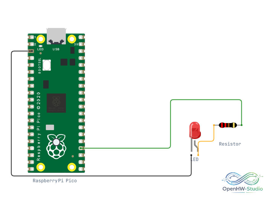
Wiring Diagram (Blink Example)
A typical configuration for testing digital output.
- Connect a 220-ohm resistor to pin GP18.
- Connect the other end of the resistor to the Anode of an LED.
- Connect the Cathode of the LED to GND.
Example Code
This code demonstrates a standard LED blink routine. In OpenHW Studio's autocoding blocks, the board's setup configuration defines GP18 as the target for led_1.
void setup() {
  // autocoding for led_1 start
  pinMode(18, OUTPUT);
  // autocoding for led_1 end

  // put your setup code here, to run once:
}

void loop() {
  // autocoding for led_1 start
  digitalWrite(18, HIGH);
  delay(1000);
  digitalWrite(18, LOW);
  delay(1000);
  // autocoding for led_1 end

  // put your main code here, to run repeatedly:
}
Simulation Notes
- To use the Raspberry Pi Pico in the OpenHW Studio editor, ensure you select the "Raspberry Pi Pico" board from the environment dropdown menu.
- The simulator models the standard
delay()function to block execution accurately. - While the physical Pico features an onboard LED connected to
GP25, you can use external LEDs connected to pins likeGP18(as shown in the code above) to test basic I/O functionality.