
8-Ch Logic Analyzer
A built-in diagnostic tool to visualize up to 8 digital signals simultaneously on a virtual oscilloscope interface.
Component Preview
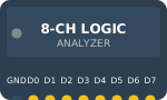 Logic Analyzer
The Logic Analyzer is not a physical part of your final circuit, but rather a powerful virtual diagnostic tool. By connecting its pins to data lines (like I2C, SPI, or PWM outputs), you can visually graph the high/low state transitions over time.
Overview
When a circuit isn't behaving as expected, a logic analyzer lets you "see" the invisible digital pulses. The OpenHW Studio logic analyzer supports 8 concurrent channels, perfect for debugging 8-bit shift registers or complex communication buses.
Pin Reference
| Pin | Type | Description |
|---|---|---|
| GND | power | Ground reference. Connect to Arduino GND. |
| D0 | digital | Channel 0 Input. |
| D1 | digital | Channel 1 Input. |
| D2 | digital | Channel 2 Input. |
| D3 | digital | Channel 3 Input. |
| D4 | digital | Channel 4 Input. |
| D5 | digital | Channel 5 Input. |
| D6 | digital | Channel 6 Input. |
| D7 | digital | Channel 7 Input. |
Configurable Attributes
This component has no standard configurable attributes.
Working Principle
The analyzer continuously samples the voltage on pins D0-D7. If the voltage is above a certain threshold (logic HIGH), it draws a high line. If below (logic LOW), it draws a low line. In the simulator, the timing is perfectly synchronized with the virtual clock.
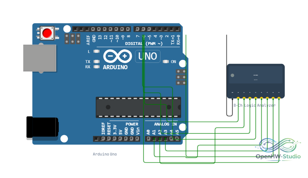
Wiring Diagram
- Connect GND to your circuit's ground.
- Connect D0 to the data line you want to monitor (e.g., Arduino D9 for a PWM signal).
- Connect D1-D7 to any other signals of interest.
Example Arduino Code
You do not write code for the logic analyzer. Instead, you write code for your microcontroller and use the analyzer to verify the output. For example, to verify a PWM signal:
void setup() {
  pinMode(9, OUTPUT);
}

void loop() {
  // Generate a 25% duty cycle PWM signal on pin 9
  // Connect D0 of the Logic Analyzer to pin 9 to see the waveform!
  analogWrite(9, 64);
}
Simulation Notes
- In the simulator, click on the Logic Analyzer component during runtime to open the graphical waveform viewer.
- You can zoom in and out of the timeline to measure pulse widths in milliseconds or microseconds.