
D Flip-Flop (Set/Reset)
A full-featured digital memory element that captures data on a clock edge, with asynchronous Set and Reset pins.
Component Preview
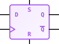 D Flip-Flop (SR)
This is a complete D Flip-Flop featuring both asynchronous Set (S) and Reset (R) pins. These pins allow you to force the flip-flop into a specific state independently of the clock signal.
Logic ComponentsSequential LogicMemory
Overview
The Set/Reset variant is commonly found in shift registers and state machines where the entire circuit must be initialized to a specific binary pattern (e.g., loading a starting value) before clocked operations begin.
Pin Reference
| Pin | Type | Description |
|---|---|---|
| D | input | Data Input. The logic value to be stored on a clock edge. |
| CLK | input | Clock Input. Triggers data capture on the rising edge. |
| S | input | Asynchronous Set. When HIGH, forces Q to HIGH. |
| R | input | Asynchronous Reset. When HIGH, forces Q to LOW. |
| Q | digital | The current stored state. |
| Q' | digital | The inverted stored state (NOT Q). |
Configurable Attributes
This component currently has no configurable attributes.
Working Principle
State Transition Table
| S (Set) | R (Reset) | CLK (Edge) | D | Q (Next State) | Q' (Next State) |
|---|---|---|---|---|---|
| 1 | 0 | X | X | 1 | 0 |
| 0 | 1 | X | X | 0 | 1 |
| 1 | 1 | X | X | Invalid | Invalid |
| 0 | 0 | ↑ (Rising) | 0 | 0 | 1 |
| 0 | 0 | ↑ (Rising) | 1 | 1 | 0 |
| 0 | 0 | 0, 1, ↓ | X | No Change (Q) | No Change (Q') |
- Asynchronous Overrides: S and R override the clock.
- Invalid State: Activating both Set and Reset simultaneously leads to an undefined or invalid state in physical hardware. The simulator will typically output LOW for both Q and Q' in this state, but it should be avoided.
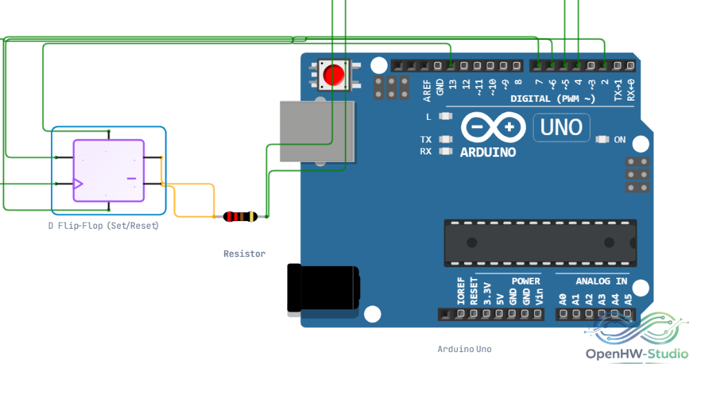
Wiring Diagram
Example Arduino Code
cpp
const int pinD = 2;   // Data Input
const int pinCLK = 3; // Clock Input
const int pinS = 4;   // Set Input
const int pinR = 5;   // Reset Input
const int pinQ = 6;   // State Output

bool lastClkState = LOW;
bool stateQ = LOW;

void setup() {
  pinMode(pinD, INPUT);
  pinMode(pinCLK, INPUT);
  pinMode(pinS, INPUT);
  pinMode(pinR, INPUT);
  pinMode(pinQ, OUTPUT);
}

void loop() {
  bool currentClkState = digitalRead(pinCLK);
  bool setState = digitalRead(pinS);
  bool resetState = digitalRead(pinR);

  // Asynchronous Priority
  if (setState == HIGH && resetState == LOW) {
    stateQ = HIGH;
  }
  else if (resetState == HIGH && setState == LOW) {
    stateQ = LOW;
  }
  // Detect Rising Edge
  else if (setState == LOW && resetState == LOW && currentClkState == HIGH && lastClkState == LOW) {
    stateQ = digitalRead(pinD);
  }

  // Drive Output
  digitalWrite(pinQ, stateQ);

  lastClkState = currentClkState;
}
Simulation Notes
- The Set and Reset pins act immediately.
- Floating pins cause unpredictable behavior. Connect unused Set/Reset pins to Ground.
Notes / Warnings
- Race Conditions: Ensure S and R are not toggled simultaneously to prevent metastability.