
Breadboard (Mini)
A highly compact solderless breadboard. Perfect for isolated sub-circuits or mounting on top of a robot chassis.
Component Preview
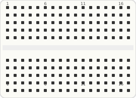 170 Tie-Points
The Mini Breadboard operates on the exact same principles as a standard breadboard, but it lacks the dedicated horizontal power rails. It provides 17 columns of 5-hole terminal strips, split down the middle.
Overview
Because of its small size (usually 4.5cm x 3.5cm), this board is often used as a breakout module for a specific sensor array or to act as an expansion on top of a motor shield where space is tight.
Pin Reference (Summarized)
A breadboard does not have active pins, but rather "tie-points" grouped into connected nodes.
| Area | Type | Description |
|---|---|---|
| Terminal Strips A-E | passive | The top half of the grid. Columns 1 through 17 run vertically. For example, holes 1A, 1B, 1C, 1D, and 1E are all electrically connected to each other. |
| Terminal Strips F-J | passive | The bottom half of the grid. Note that hole 1F is NOT connected to hole 1E. The ravine in the center isolates the top half from the bottom half. |
| Power Rails | passive | None. You must dedicate one or more vertical columns if you need a common power or ground bus. |
Wiring Diagram
Configurable Attributes
| Attribute | Type | Default | Description |
|---|---|---|---|
| color | string | "white" | Changes the visual color of the breadboard plastic in the simulator (e.g., "white", "black", "transparent"). |
Working Principle
Inside the mini breadboard are vertical metal spring clips connecting groups of 5 holes at a time. The center gap (the ravine) is exactly the right size to straddle a small Dual In-Line Package (DIP) IC chip. Because there are no power rails, building large circuits can quickly turn into a mess of overlapping wires.
Wiring Guide
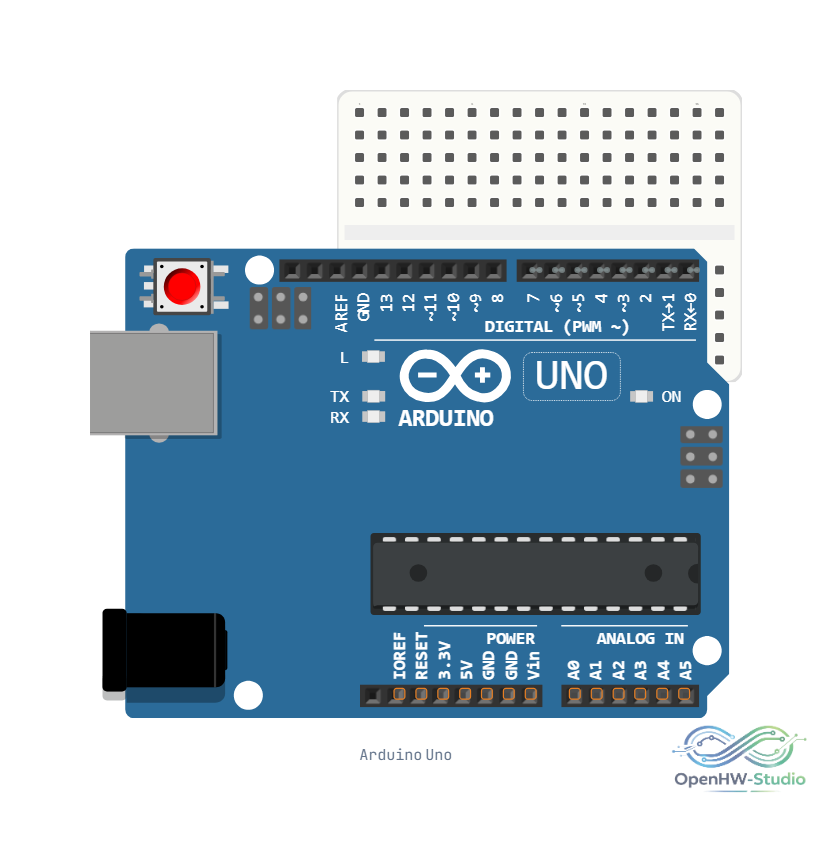
- Dedicate column 1 (for example) to be your Ground rail, and column 17 to be your 5V power rail.
- Route power from your Arduino into these designated columns.
- Use short jumper wires to distribute power from those columns to the components on the board.
Simulation Notes
- Just like the half-size breadboard, hovering over a hole in the simulator will highlight all other holes that are electrically connected to it in green.
- Snap small ICs and sensors directly into the holes to keep your workspace clean.
Example Code
void setup() {
  // Setup code
}

void loop() {
  // Loop code
}