
I2S MEMS Microphone (INMP441)
A digital microphone with an I2S interface, providing high signal-to-noise ratio and wide frequency response.
Component Preview
 I2S Microphone
Unlike standard analog microphones that require an ADC, the INMP441 outputs a digital I2S audio stream directly. This allows microcontrollers like the ESP32 to record high-quality audio directly from the sensor without noise degradation.
Overview
The I2S (Inter-IC Sound) interface is an electrical serial bus interface standard used for connecting digital audio devices together. The INMP441 requires three data/clock lines to operate, making it ideal for voice recognition or audio recording projects.
Pin Reference
| Pin | Type | Description |
|---|---|---|
| VDD | power | Power supply (1.8V to 3.3V). |
| GND | power | Ground connection. |
| L/R | digital | Left/Right Channel Select. Connect to GND for Left, VDD for Right. |
| WS | digital | Word Select (Left-Right Clock). Indicates the channel currently being transmitted. |
| SCK | digital | Serial Data Clock. |
| SD | digital | Serial Data Output. The actual audio bitstream. |
Configurable Attributes
This component has no standard configurable attributes in the simulator. The simulator feeds pre-recorded noise or sine waves to emulate audio input.
Working Principle
The INMP441 converts sound waves into a continuous stream of digital audio samples. The host microcontroller (e.g., ESP32) generates the SCK (clock) and WS (word select) signals to read the data from the SD pin exactly in sync with the audio sampling rate.
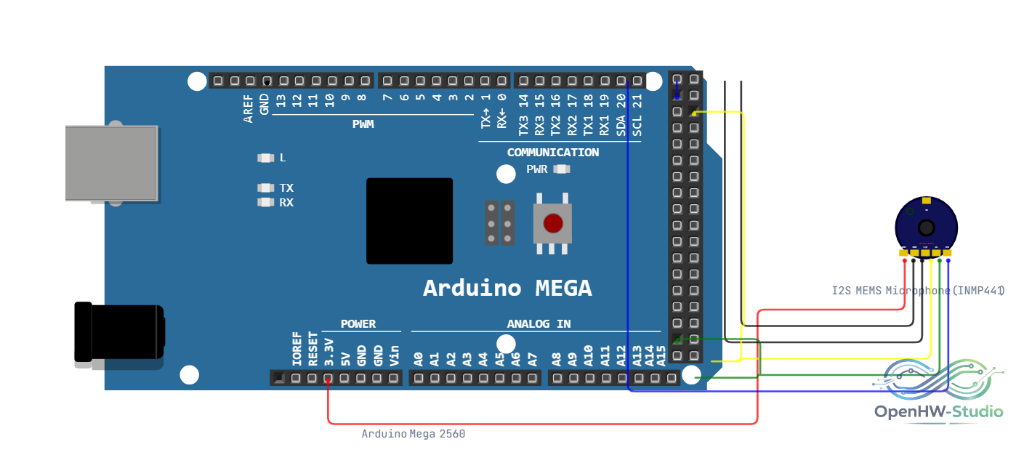
Wiring Diagram (ESP32)
- Connect VDD to 3.3V and GND to Ground.
- Connect L/R to Ground (sets it to the Left channel).
- Connect WS to GPIO 15.
- Connect SCK to GPIO 14.
- Connect SD to GPIO 32.
Example Arduino Code (ESP32)
This code uses the ESP32's built-in I2S peripheral to read data from the microphone.
#include <driver/i2s.h>

const i2s_port_t I2S_PORT = I2S_NUM_0;

void setup() {
  Serial.begin(115200);

  i2s_config_t i2s_config = {
    .mode = (i2s_mode_t)(I2S_MODE_MASTER | I2S_MODE_RX),
    .sample_rate = 16000,
    .bits_per_sample = I2S_BITS_PER_SAMPLE_32BIT,
    .channel_format = I2S_CHANNEL_FMT_ONLY_LEFT,
    .communication_format = I2S_COMM_FORMAT_STAND_I2S,
    .intr_alloc_flags = ESP_INTR_FLAG_LEVEL1,
    .dma_buf_count = 8,
    .dma_buf_len = 64,
    .use_apll = false,
    .tx_desc_auto_clear = false,
    .fixed_mclk = 0
  };

  i2s_pin_config_t pin_config = {
    .bck_io_num = 14,   // SCK
    .ws_io_num = 15,    // WS
    .data_out_num = I2S_PIN_NO_CHANGE,
    .data_in_num = 32   // SD
  };

  i2s_driver_install(I2S_PORT, &i2s_config, 0, NULL);
  i2s_set_pin(I2S_PORT, &pin_config);

  Serial.println("I2S Microphone Ready");
}

void loop() {
  int32_t sample = 0;
  size_t bytesRead = 0;

  // Read a single 32-bit sample from the microphone
  esp_err_t result = i2s_read(I2S_PORT, &sample, sizeof(int32_t), &bytesRead, portMAX_DELAY);

  if (result == ESP_OK && bytesRead > 0) {
    // The data is 24-bit, stored in the upper 24 bits of the 32-bit integer
    sample = sample >> 8;

    // Print it so the Serial Plotter can graph the audio wave
    Serial.println(sample);
  }
}
Simulation Notes
- Because browsers don't expose raw I2S bitstreams easily, the simulator injects a mathematically generated sine wave into the emulated I2S peripheral of the microcontroller, allowing your code to "hear" audio data.