
Buffer Gate
A digital logic buffer gate that outputs the exact logic level of its input, providing electrical isolation or signal drive strength.
Component Preview
 Buffer Gate
A logic gate that performs no logical operation on the input signal. It simply passes the HIGH or LOW state through. It is typically used in hardware to boost signal strength, isolate circuits, or add a small propagation delay.
Overview
The Buffer Gate (also known as a non-inverting buffer) is a single-input, single-output digital component. In the OpenHW Studio simulator, it is useful for separating different segments of a logic circuit or simply acting as a pass-through wire with gate-like properties.
Pin Reference
| Pin | Type | Description |
|---|---|---|
| IN | input | Digital logic input. Expects HIGH (1) or LOW (0). |
| OUT | digital | Digital logic output. Driven to the exact same state as IN. |
Configurable Attributes
This component currently has no configurable attributes.
Working Principle
Truth Table
| IN | OUT |
|---|---|
| 0 (LOW) | 0 (LOW) |
| 1 (HIGH) | 1 (HIGH) |
The Boolean expression for a buffer is simply Y = A. Whatever logic level is applied to the input is mirrored on the output.
Wiring Diagram
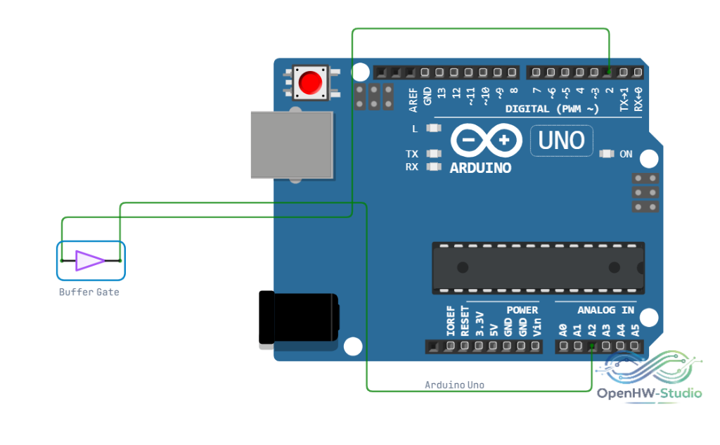
Example Arduino Code
To test the Buffer gate using an Arduino, apply a signal to the input and read it back from the output.
const int pinIn = 2;  // Connect to IN of Buffer Gate
const int pinOut = 3; // Connect to OUT of Buffer Gate

void setup() {
  Serial.begin(9600);
  pinMode(pinIn, OUTPUT);
  pinMode(pinOut, INPUT);
  Serial.println("Buffer Gate Truth Table Test:");
}

void loop() {
  // Test LOW state
  digitalWrite(pinIn, LOW);
  delay(10); // Propagation delay
  Serial.print("IN: 0 => OUT: ");
  Serial.println(digitalRead(pinOut));
  delay(1000);

  // Test HIGH state
  digitalWrite(pinIn, HIGH);
  delay(10);
  Serial.print("IN: 1 => OUT: ");
  Serial.println(digitalRead(pinOut));
  delay(1000);
}
Simulation Notes
- The Buffer gate component in the simulator evaluates the logic state instantaneously.
- If the input is left floating (disconnected), the output state may be undefined or default to LOW depending on the simulation engine settings.
Notes / Warnings
- Voltage Levels: The simulator treats standard logic signals as valid inputs. Do not apply analog voltages between logic thresholds, as this is purely a digital component.
- Drive Strength: In real hardware, buffers increase current drive capability. In simulation, all digital outputs have infinite drive strength by default unless specified otherwise by the pin configuration.