
A4988 Stepper Motor Driver
A widely-used microstepping driver module for controlling bipolar stepper motors precisely.
Component Preview
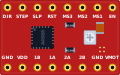 A4988 Module
The A4988 is a microstepping motor driver with a built-in translator. It allows you to control a complex bipolar stepper motor using just two pins from your microcontroller: one for controlling rotational direction, and one for stepping.
Overview
Stepper motors require specific sequences of high-current pulses to rotate. The A4988 driver handles this heavy lifting. By providing it with a motor power supply and logic signals, it safely drives the motor coils and even allows for "microstepping" (subdividing a single step into smaller steps for smoother motion).
Pin Reference
| Pin | Type | Description |
|---|---|---|
| VMOT | power | Motor power supply (8V - 35V). |
| GND_MOT | power | Motor ground. |
| VDD | power | Logic power supply (3.3V or 5V). |
| GND_LOGIC | power | Logic ground. (Should be tied to Motor ground). |
| 1A, 1B | analog | Connect to Coil 1 of the stepper motor. |
| 2A, 2B | analog | Connect to Coil 2 of the stepper motor. |
| STEP | digital | Step input. A LOW-to-HIGH transition advances the motor one step. |
| DIR | digital | Direction input. HIGH = Clockwise, LOW = Counter-Clockwise. |
| ENABLE | digital | Active LOW. Enables the driver outputs. Usually tied to GND or left floating (internal pull-down). |
| RESET | digital | Active LOW. Resets the internal logic. Usually tied to SLEEP. |
| SLEEP | digital | Active LOW. Puts the driver to sleep. Usually tied to RESET. |
| MS1, MS2, MS3 | digital | Microstepping resolution pins. |
Configurable Attributes
This component currently has no configurable attributes in the simulator.
Working Principle
The A4988 reads the DIR pin to determine which way to sequence the coils. Every time the STEP pin receives a rising edge (goes from LOW to HIGH), the internal translator advances the motor's coils to the next position in the sequence, rotating the motor shaft by a small, precise angle.
Wiring Diagram
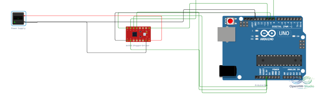
Connect the A4988 to the Arduino, your stepper motor, and an external power supply.
Example Arduino Code
const int dirPin = 8;
const int stepPin = 9;

void setup() {
  pinMode(dirPin, OUTPUT);
  pinMode(stepPin, OUTPUT);
}

void loop() {
  // Move 200 steps Clockwise (1 full revolution for standard steppers)
  digitalWrite(dirPin, HIGH);
  for (int i = 0; i < 200; i++) {
    digitalWrite(stepPin, HIGH);
    delayMicroseconds(1000); // Speed of the step
    digitalWrite(stepPin, LOW);
    delayMicroseconds(1000);
  }

  delay(1000); // Pause for 1 second

  // Move 200 steps Counter-Clockwise
  digitalWrite(dirPin, LOW);
  for (int i = 0; i < 200; i++) {
    digitalWrite(stepPin, HIGH);
    delayMicroseconds(1000);
    digitalWrite(stepPin, LOW);
    delayMicroseconds(1000);
  }

  delay(1000);
}
Simulation Notes
- In the simulator, the A4988 operates instantly without thermal limits.
- If you pair this driver with a Stepper Motor component in the simulator, you will see the motor shaft rotate visually based on your pulse timings.
Notes / Warnings
- Real-World Warning: Never disconnect or connect a stepper motor while the driver is powered. This causes a massive voltage spike that will instantly destroy the A4988 chip.